Cirkit Designer
Your all-in-one circuit design IDE
Home /
Project Documentation
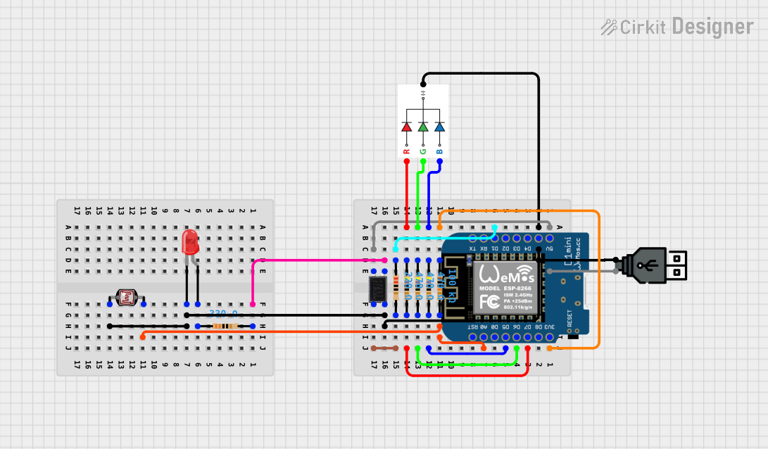
Wi-Fi Enabled RGB and Red LED Controller with Light Sensing
Circuit Documentation
Summary
This document provides a detailed overview of a circuit designed to interface an RGB LED, a red two-pin LED, an octocoupler, various resistors, a photocell (LDR), a USB power source, and a Wemos D1 Mini microcontroller. The circuit is powered via USB and includes signal conditioning and interfacing components to demonstrate various functionalities such as light sensing and LED control.
Component List
RGB LED
- Pins: Blue (B), Green (G), Red (R), Ground (GND)
- Description: A light-emitting diode that can emit red, green, and blue colors.
LED: Two Pin (red)
- Pins: Cathode, Anode
- Description: A standard red indicator LED.
Octocoupler
- Pins: Anode, Cathode, Collector, Emitter
- Description: An electronic component that transfers electrical signals between two isolated circuits by using light.
Resistor (330 Ohms)
- Pins: pin1, pin2
- Description: A resistor with a resistance of 330 Ohms.
Photocell (LDR)
- Pins: pin 0, pin 1
- Description: A light-dependent resistor whose resistance changes based on light intensity.
Resistor (100k Ohms)
- Pins: pin1, pin2
- Description: A resistor with a resistance of 100,000 Ohms.
Resistor (470 Ohms)
- Pins: pin1, pin2
- Description: A resistor with a resistance of 470 Ohms.
USB power
- Pins: Positive (+), Negative (-)
- Description: A USB power source for the circuit.
Resistor (220 Ohms)
- Pins: pin1, pin2
- Description: A resistor with a resistance of 220 Ohms.
Wemos D1 Mini
- Pins: RST, A0, D0, D5, D6, D7, D8, 3V3, 5V, G, D4, D3, D2, D1, RX, TX
- Description: A compact microcontroller based on the ESP8266, with Wi-Fi capabilities.
Wiring Details
RGB LED
- Blue (B) connected to Resistor (470 Ohms)
- Green (G) connected to Resistor (470 Ohms)
- Red (R) connected to Resistor (470 Ohms)
- Ground (GND) connected to USB power Negative (-)
LED: Two Pin (red)
- Cathode connected to Photocell (LDR) pin 0, Wemos D1 Mini Ground (G), Octocoupler Cathode, USB power Negative (-)
- Anode connected to Resistor (330 Ohms)
Octocoupler
- Anode connected to Resistor (220 Ohms)
- Cathode connected to LED: Two Pin (red) Cathode
- Collector connected to Wemos D1 Mini 5V, USB power Positive (+)
- Emitter connected to Resistor (330 Ohms)
Resistor (330 Ohms)
- Pin1 connected to LED: Two Pin (red) Anode
- Pin2 connected to Octocoupler Emitter
Photocell (LDR)
- Pin 0 connected to LED: Two Pin (red) Cathode
- Pin 1 connected to Resistor (100k Ohms) pin2, Wemos D1 Mini A0
Resistor (100k Ohms)
- Pin1 connected to Wemos D1 Mini 3V3
- Pin2 connected to Photocell (LDR) pin 1
Resistor (470 Ohms)
- Three instances, each connected between Wemos D1 Mini pins D5, D6, D7 and the corresponding RGB LED pins B, G, R.
USB power
- Positive (+) connected to Octocoupler Collector
- Negative (-) connected to LED: Two Pin (red) Cathode, RGB LED Ground (GND)
Resistor (220 Ohms)
- Pin1 connected to Wemos D1 Mini D1
- Pin2 connected to Octocoupler Anode
Wemos D1 Mini
- 5V connected to Octocoupler Collector, USB power Positive (+)
- 3V3 connected to Resistor (100k Ohms) pin1
- G connected to LED: Two Pin (red) Cathode
- D5 connected to Resistor (470 Ohms) pin2
- D6 connected to Resistor (470 Ohms) pin2
- D7 connected to Resistor (470 Ohms) pin2
- A0 connected to Photocell (LDR) pin 1
- D1 connected to Resistor (220 Ohms) pin1
Documented Code
Wemos D1 Mini (sketch.ino)
void setup() {
  // put your setup code here, to run once:

}

void loop() {
  // put your main code here, to run repeatedly:

}
Additional Notes
- The code provided for the Wemos D1 Mini is a template with empty setup and loop functions. This code needs to be populated with the logic to control the RGB LED and read the photocell sensor values.
- The documentation file for the Wemos D1 Mini is empty and should be filled with relevant information about the microcontroller's role in the circuit, including how it interfaces with the other components.