
Circuit Documentation
Summary of the Circuit
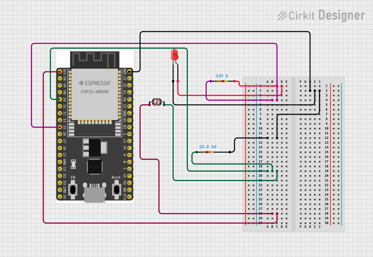
The circuit described by the provided inputs appears to be a simple light-sensitive LED circuit controlled by an ESP32 microcontroller. The circuit includes a light-dependent resistor (LDR), also known as a photocell, which changes resistance based on the amount of light it detects. This variable resistance is used by the ESP32 to determine when to turn an LED on or off. The LED is connected in series with a current-limiting resistor to protect it from excessive current. Another resistor is used in series with the LDR to form a voltage divider, which allows the ESP32 to read the light levels as an analog voltage.
Component List
Resistor (220 Ohms)
- Description: A resistor with a resistance of 220 Ohms, typically used to limit current.
- Pins: pin1, pin2
Resistor (10 kOhms)
- Description: A resistor with a resistance of 10 kOhms, often used as a pull-up or pull-down resistor or in voltage dividers.
- Pins: pin1, pin2
ESP 32 Wroom Dev Kit
- Description: A development board based on the ESP32 microcontroller, which is a powerful, generic Wi-Fi+BT+BLE MCU module that targets a wide variety of applications.
- Pins: 3V3, EN, VP, VN, GPIO 34, GPIO 35, GPIO 32, GPIO 33, GPIO 25, GPIO 26, GPIO 27, GPIO 14, GND, GPIO 13, SD2, SD3, CMD, V5, GPIO 23, GPIO 22, TXD, RXD, GPIO 21, GPIO 19, GPIO 18, GPIO 5, GPIO 17, GPIO 16, GPIO 4, GPIO 0, GPIO 2, GPIO 15, SD1, SD0, CLK
LED: Two Pin (red)
- Description: A red LED used as an indicator or for illumination.
- Pins: cathode, anode
Photocell (LDR)
- Description: A light-dependent resistor whose resistance changes with light intensity.
- Pins: pin 0, pin 1
Wiring Details
Resistor (220 Ohms)
- pin2 is connected to the anode of the LED.
- pin1 is connected to GPIO 25 of the ESP 32 Wroom Dev Kit.
Resistor (10 kOhms)
- pin2 is connected to the cathode of the LED, GND of the ESP 32 Wroom Dev Kit.
- pin1 is connected to GPIO 34 of the ESP 32 Wroom Dev Kit and pin 1 of the Photocell (LDR).
ESP 32 Wroom Dev Kit
- GND is connected to the cathode of the LED and pin2 of the 10 kOhms resistor.
- GPIO 25 is connected to pin1 of the 220 Ohms resistor.
- GPIO 34 is connected to pin1 of the 10 kOhms resistor and pin 1 of the Photocell (LDR).
- 3V3 is connected to pin 0 of the Photocell (LDR).
LED: Two Pin (red)
- anode is connected to pin2 of the 220 Ohms resistor.
- cathode is connected to pin2 of the 10 kOhms resistor and GND of the ESP 32 Wroom Dev Kit.
Photocell (LDR)
- pin 1 is connected to pin1 of the 10 kOhms resistor and GPIO 34 of the ESP 32 Wroom Dev Kit.
- pin 0 is connected to 3V3 of the ESP 32 Wroom Dev Kit.
Documented Code
No code was provided for the microcontroller. To complete the documentation, the code for the ESP32 microcontroller should be included, which would typically read the analog voltage from the LDR voltage divider, process the reading to determine the light level, and then control the LED accordingly. Since no code is available, this section cannot be completed at this time.