
Arduino UNO Controlled LED Blinker with 74HC595 Shift Register
View and Edit Project In Cirkit Designer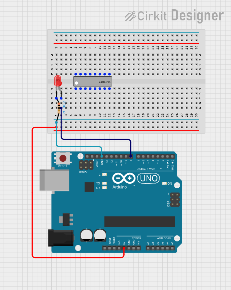
Circuit Documentation
Summary
This document provides a detailed overview of a simple circuit that includes an Arduino UNO microcontroller, a 74HC595 shift register, a red LED, and a resistor. The circuit is designed to control the LED using one of the digital pins on the Arduino UNO. The Arduino is programmed to toggle the LED on and off, demonstrating basic digital output functionality.
Component List
Arduino UNO
- Description: A microcontroller board based on the ATmega328P.
- Pins: UNUSED, IOREF, Reset, 3.3V, 5V, GND, Vin, A0-A5, SCL, SDA, AREF, D0-D13.
74HC595 Shift Register
- Description: An 8-bit serial-in, serial or parallel-out shift register with output latches.
- Pins: Q0-Q7, GND, VCC, DS (DATA), OE (Enable), ST_CP (RCLK), SH_CP (SRCLK), MR (SRCLR), Q7' (QH).
LED: Two Pin (red)
- Description: A basic red LED.
- Pins: Anode, Cathode.
Resistor
- Description: A passive two-terminal electrical component that implements electrical resistance as a circuit element.
- Pins: Pin1, Pin2.
- Properties: Resistance - 200 Ohms.
Wiring Details
Arduino UNO
- D8 connected to the anode of the LED.
- 5V and GND are power supply pins.
- GND is also connected to one end of the resistor.
74HC595 Shift Register
- No connections specified in the provided net list.
LED: Two Pin (red)
- Anode connected to Arduino UNO's D8.
- Cathode connected to one end of the resistor.
Resistor
- Pin1 connected to the cathode of the LED.
- Pin2 connected to the GND of the Arduino UNO.
- Value: 200 Ohms.
Documented Code
Arduino UNO Code (sketch.ino)
/**********************************************************
 * Arduino ports
 **********************************************************/
#pragma region define(s)

#define TITLE               "Arduino ports \n-------------- \n"
#define BUFF_SIZE           100             // bytes

#define PIN00  0
#define PIN01  1
#define PIN02  2
#define PIN03  3
#define PIN04  4
#define PIN05  5
#define PIN06  6
#define PIN07  7
#define PIN08  8
#define PIN09  9
#define PIN10  10
#define PIN11  11
#define PIN12  12
#define PIN13  13
#define PIN14  14
#define PIN15  15
#define PINS_PER_PORT  8

#define INPUT   0
#define OUTPUT  1
#define LOW     0
#define HIGH    1

#pragma endregion

#pragma region util

/*
 * getByte()
 */
unsigned char getByte(unsigned char pin) {
    return 1 << (pin % PINS_PER_PORT);
}  // getByte()

/*
 * getPort()
 */
volatile unsigned char & getPort(unsigned char pin) {
    if ((pin >= PIN00) && (pin <= PIN07)) {
        return PORTD;
    }  // if
    else {
        return PORTB;
    }  // if
}  // getPort()

/*
 * serialPrint()
 */
void serialPrint(const char * msg) {
    Serial.print(msg);
}  // serialPrint()

void serialPrint(const char * msg, int number) {
    char buff[BUFF_SIZE];
    sprintf(buff, msg, number);
    serialPrint(buff);
}  // serialPrint()

#pragma endregion

#pragma region program

/*
 * setup()
 */
void setup() {
    Serial.begin(9600);
    serialPrint(TITLE);
    serialPrint("setup() \n");

    // set pin(s) 8 as output
    DDRB = (1<< PINB0);

    // set pin 12 high
    PORTB = (1<< PINB0);
}  // setup()

/*
 * use_ports()
 */
void use_ports() {
    PORTB &= ~(1<< PINB0);
    serialPrint("PORTB = 0x%02x \n", PORTB);
    _delay_ms(500);
    PORTB |= (1<< PINB0);
    serialPrint("PORTB = 0x%02x \n", PORTB);
    _delay_ms(500);
}  // use_ports()

/*
 * main()
 */
int main() {
    setup();

    // int i = 0;
    while (1) {
        use_ports();
    }  // while()
}  // main()

#pragma endregion
Note: The code provided is for the Arduino UNO microcontroller. It initializes the serial communication, sets up pin 8 as an output, and toggles it to control the LED. The main function contains an infinite loop that calls use_ports to toggle the LED on and off with a delay of 500 milliseconds.