
Circuit Documentation
Summary of the Circuit
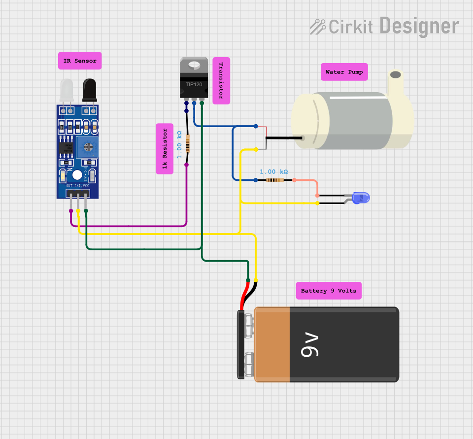
This circuit appears to be designed to control a mini water pump using an infrared sensor (FC-51 IR) and a TIP120 Darlington Transistor as a switch. The sensor detects the presence of an object, and upon detection, it likely triggers the transistor to power the pump. Additionally, there is an LED indicator in the circuit, which might be used to signal the sensor's state or the pump's activity. The circuit is powered by a 9V battery, and it includes resistors for current limiting purposes.
Component List
Sensor FC-51 IR
- Description: Infrared sensor module used for object detection.
- Pins: OUT, GND, VCC
TIP120 Hi-Current Darlington Transistor
- Description: A transistor used for controlling high current loads.
- Pins: BASE, COLLECTOR, EMITTER
Mini Water Pump
- Description: A pump that is likely controlled by the transistor.
- Pins: 5V, GND
Resistors (2x)
- Description: Resistors used for current limiting and voltage division.
- Value: 1000 Ohms each
LED: Two Pin (blue)
- Description: A blue LED used as an indicator.
- Pins: cathode, anode
9V Battery
- Description: Power source for the circuit.
- Pins: -, +
Comments (6x)
- Description: Placeholder components for annotations or notes.
Wiring Details
Sensor FC-51 IR
- OUT connected to one end of a 1000 Ohm resistor.
- GND connected to the negative terminal of the 9V battery, GND of the mini water pump, and anode of the LED.
- VCC connected to the EMITTER of the TIP120 transistor and the positive terminal of the 9V battery.
TIP120 Hi-Current Darlington Transistor
- BASE connected to the other end of the 1000 Ohm resistor connected to the OUT pin of the sensor.
- COLLECTOR connected to the 5V pin of the mini water pump and one end of a 1000 Ohm resistor.
- EMITTER connected to the VCC of the sensor and the positive terminal of the 9V battery.
Mini Water Pump
- 5V connected to the COLLECTOR of the TIP120 transistor and one end of a 1000 Ohm resistor.
- GND connected to the negative terminal of the 9V battery.
Resistors
- Resistor 1 (1000 Ohms): One end connected to the OUT pin of the sensor, the other end to the BASE of the TIP120 transistor.
- Resistor 2 (1000 Ohms): One end connected to the COLLECTOR of the TIP120 transistor, the other end to the cathode of the LED.
LED: Two Pin (blue)
- cathode connected to one end of a 1000 Ohm resistor.
- anode connected to the negative terminal of the 9V battery.
9V Battery
- - (negative terminal) connected to the GND of the sensor, the GND of the mini water pump, and the anode of the LED.
- + (positive terminal) connected to the VCC of the sensor and the EMITTER of the TIP120 transistor.
Documented Code
There is no embedded code provided for any microcontrollers in this circuit. If the circuit is intended to be controlled by a microcontroller, the code would be necessary to define the behavior of the sensor and the subsequent control of the pump and LED indicator. Without the code, the circuit's operation relies on the inherent behavior of the components and their wiring.