
Battery-Powered Motion-Activated Light with HC-SR501 and NPN Transistor
View and Edit Project In Cirkit Designer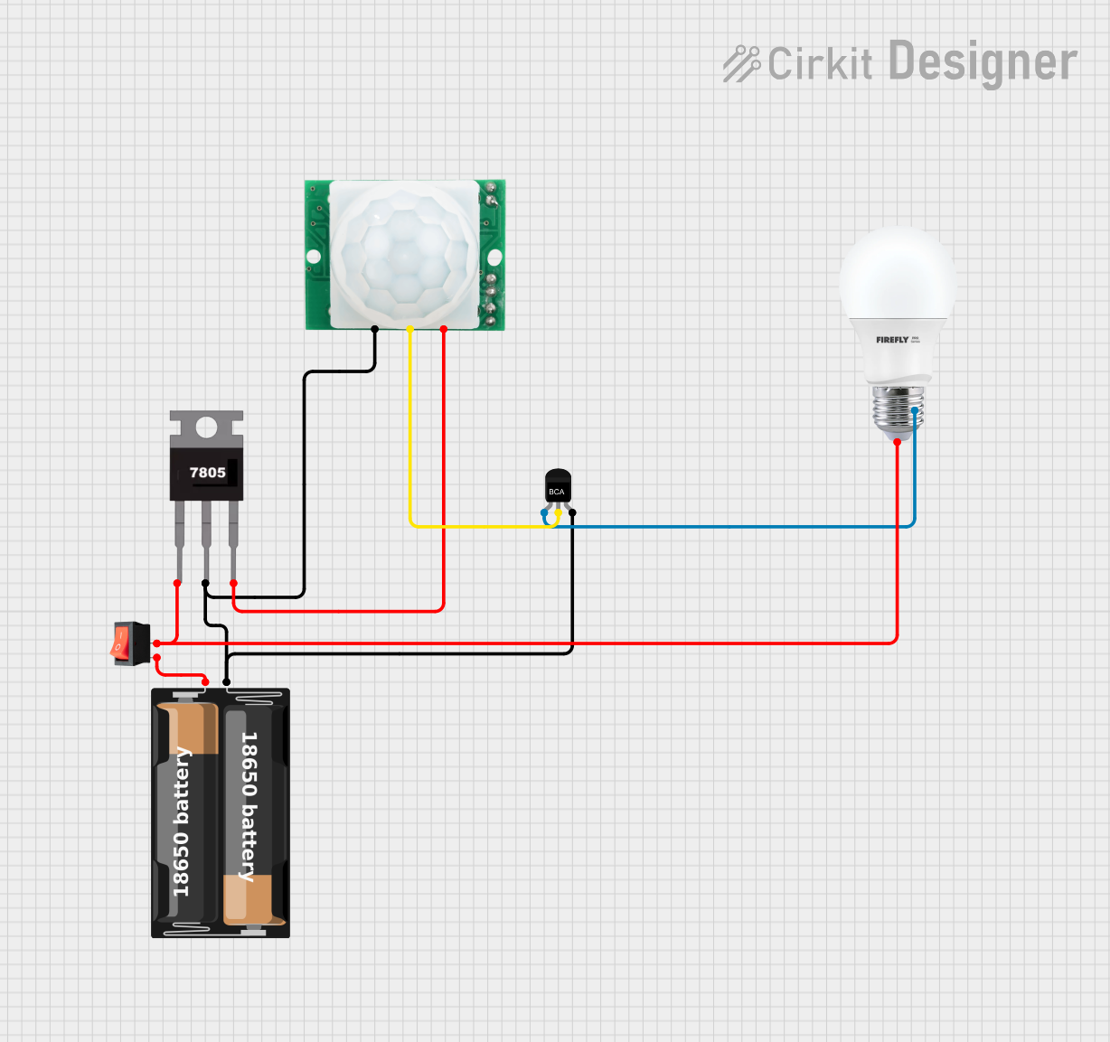
Circuit Documentation
Summary
This circuit is designed to control a bulb using a motion sensor and a transistor. The circuit includes a power supply, a voltage regulator, a motion sensor, a transistor, a bulb, and a rocker switch. When motion is detected by the HC-SR501 motion sensor, it triggers the NPN transistor, which in turn powers the bulb. The 7805 voltage regulator ensures that the motion sensor receives a stable 5V supply.
Component List
HC-SR501 Motion Sensor
- Pins: GND, OUT, VCC
- Description: A motion sensor that detects infrared radiation and outputs a signal when motion is detected.
- Purpose in Circuit: Detects motion and sends a signal to the transistor.
NPN Transistor
- Pins: E (Emitter), C (Collector), B (Base)
- Description: A type of bipolar junction transistor used for switching and amplification.
- Purpose in Circuit: Acts as a switch to control the bulb based on the signal from the motion sensor.
Battery Case
- Pins: +, -
- Description: Holds the batteries that provide power to the circuit.
- Purpose in Circuit: Supplies power to the entire circuit.
Bulb
- Pins: +, -
- Description: A light bulb that illuminates when powered.
- Purpose in Circuit: Provides visual indication when the circuit is activated.
7805 Voltage Regulator
- Pins: Vin, Gnd, Vout
- Description: A voltage regulator that outputs a stable 5V.
- Purpose in Circuit: Provides a stable 5V supply to the motion sensor.
Rocker Switch
- Pins: input, output
- Description: A switch that can be toggled to connect or disconnect the circuit.
- Purpose in Circuit: Allows manual control to turn the circuit on or off.
Wiring Details
HC-SR501 Motion Sensor
GND is connected to:
- Gnd of the 7805 Voltage Regulator
-
- of the Battery Case
- B of the NPN Transistor
OUT is connected to:
- C of the NPN Transistor
VCC is connected to:
- Vout of the 7805 Voltage Regulator
NPN Transistor
B (Base) is connected to:
- Gnd of the 7805 Voltage Regulator
- GND of the HC-SR501 Motion Sensor
-
- of the Battery Case
C (Collector) is connected to:
- OUT of the HC-SR501 Motion Sensor
E (Emitter) is connected to:
-
- of the Bulb
-
Battery Case
+ is connected to:
- input of the Rocker Switch
- is connected to:
- Gnd of the 7805 Voltage Regulator
- GND of the HC-SR501 Motion Sensor
- B of the NPN Transistor
Bulb
+ is connected to:
- output of the Rocker Switch
- Vin of the 7805 Voltage Regulator
- is connected to:
- E of the NPN Transistor
7805 Voltage Regulator
Vin is connected to:
- output of the Rocker Switch
-
- of the Bulb
Gnd is connected to:
- GND of the HC-SR501 Motion Sensor
-
- of the Battery Case
- B of the NPN Transistor
Vout is connected to:
- VCC of the HC-SR501 Motion Sensor
Rocker Switch
input is connected to:
-
- of the Battery Case
-
output is connected to:
- Vin of the 7805 Voltage Regulator
-
- of the Bulb
Code
There is no code associated with this circuit.