
Raspberry Pi 5-Based Smart Environmental Monitoring and Medicine Reminder System
View and Edit Project In Cirkit Designer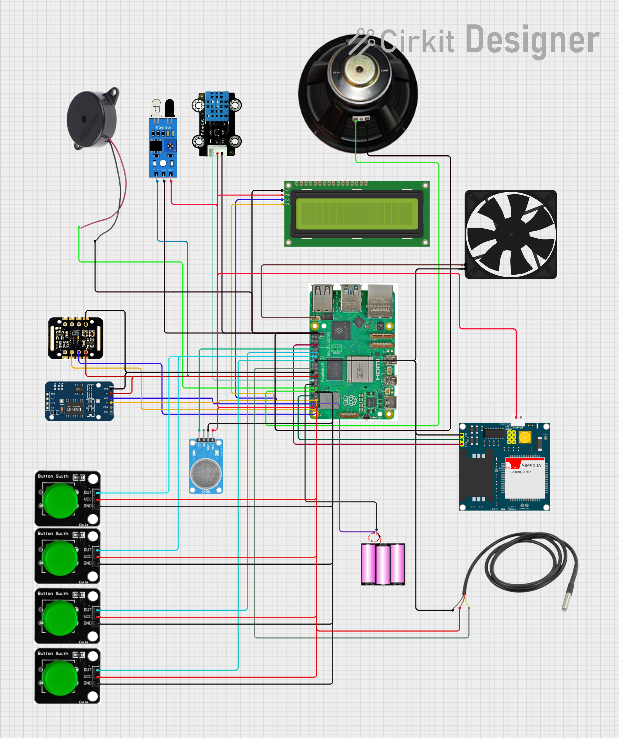
Circuit Documentation
Summary
The circuit in question is a multifunctional system designed around the Raspberry Pi 5 microcontroller. It integrates various sensors and modules to perform tasks such as environmental monitoring, gas detection, real-time clock tracking, and user interaction through buttons and a display. The system also includes communication capabilities via the SIM900A GSM module, allowing it to send SMS alerts. A buzzer and speaker provide audio feedback, and a fan is included for cooling purposes.
Component List
Battery 12V
A 12V battery provides power to the Raspberry Pi 5 and other components in the circuit.
Speaker
An audio output device used to provide sound feedback.
DS3231 RTC (Real-Time Clock)
A precision I2C real-time clock (RTC) with a built-in temperature-compensated crystal oscillator (TCXO) and crystal.
IR Sensor
An infrared sensor used for detecting obstacles or motion.
Temperature Sensor
A sensor used to measure temperature, typically with a digital interface.
Green Button
A push-button switch used for user input.
MQ-2 Sensor
A gas sensor used for detecting a variety of gases including LPG, smoke, and alcohol vapor.
MAX30102 HR + SpO2 Sensor
An integrated pulse oximetry and heart-rate monitor sensor module.
Buzzer
An audio signaling device that can be used to alert users.
MKE-S14 DHT11 Temperature And Humidity Sensor
A sensor used for measuring temperature and humidity.
Raspberry Pi 5
A powerful microcontroller that serves as the central processing unit of the circuit.
16x2 I2C LCD
A liquid crystal display that can show 16 characters per line and has 2 lines, with an I2C interface for communication.
SIM900A
A GSM/GPRS module that allows the circuit to communicate over mobile networks.
Fan
A cooling device used to maintain an optimal operating temperature for the circuit.
Wiring Details
16x2 I2C LCD
- SCL connected to Raspberry Pi 5 GPIO 3
- SDA connected to Raspberry Pi 5 GPIO 2
- GND connected to Raspberry Pi 5 GND
- VCC connected to Raspberry Pi 5 5V
DS3231 RTC
- SCL connected to Raspberry Pi 5 GPIO 3
- SDA connected to Raspberry Pi 5 GPIO 2
- VCC connected to Raspberry Pi 5 3.3V
- GND connected to Raspberry Pi 5 GND
MAX30102 HR + SpO2 Sensor
- SCL connected to Raspberry Pi 5 GPIO 3
- SDA connected to Raspberry Pi 5 GPIO 2
- VIN connected to Raspberry Pi 5 3.3V
- GND connected to Raspberry Pi 5 GND
IR Sensor
- Out connected to Raspberry Pi 5 GPIO 24
- GND connected to Raspberry Pi 5 GND
- VCC connected to Raspberry Pi 5 5V
MQ-2 Sensor
- VCC connected to Raspberry Pi 5 5V
- GND connected to Raspberry Pi 5 GND
- A0 not connected
- D0 connected to Raspberry Pi 5 GPIO 12
MKE-S14 DHT11 Temperature And Humidity Sensor
- SIG connected to Raspberry Pi 5 GPIO 23
- 5V connected to Raspberry Pi 5 5V
- GND connected to Raspberry Pi 5 GND
SIM900A
- GND connected to Raspberry Pi 5 GND
- DB9-3 (RXD) connected to Raspberry Pi 5 GPIO 14
- DB9-2 (TXD) connected to Raspberry Pi 5 GPIO 13
- 5V connected to Raspberry Pi 5 5V
Fan
- 5V connected to Raspberry Pi 5 Fan
- GND connected to Raspberry Pi 5 GND
Temperature Sensor
- Temp GND Black connected to Raspberry Pi 5 GND
- Temp VDD Red connected to Raspberry Pi 5 3.3V
- Temp DQ Data Yellow connected to Raspberry Pi 5 GPIO 25
Green Button
- OUT connected to Raspberry Pi 5 GPIO 1, GPIO 0, GPIO 5, GPIO 7 (four instances of the button)
- VCC connected to Raspberry Pi 5 3.3V
- GND connected to Raspberry Pi 5 GND
Buzzer
- POSITIVE connected to Raspberry Pi 5 GPIO 18
- NEGATIVE connected to Raspberry Pi 5 GND
Speaker
-
- connected to Raspberry Pi 5 GPIO 17
-
- connected to Raspberry Pi 5 GND
Battery 12V
-
- connected to Raspberry Pi 5 5V
-
- connected to Raspberry Pi 5 GND
Documented Code
The following code is written for the Raspberry Pi 5 microcontroller. It includes the setup and main loop for the various sensors and modules in the circuit.
# Import required libraries
import RPi.GPIO as GPIO
import time
import smtplib
from datetime import datetime
from time import sleep
import Adafruit_DHT
import serial

# Setup for sensors and modules
GPIO.setwarnings(False)
GPIO.setmode(GPIO.BCM)

# Pin configuration
buzzer_pin = 18
ir_sensor_pin = 17
button_pin = 27
lcd_rs = 21
lcd_e = 20
lcd_d4 = 5
lcd_d5 = 6
lcd_d6 = 13
lcd_d7 = 19
dht_pin = 4
mq2_pin = 23

# RTC module and temperature modules
rtc_module = DS3231()
temp_module = MAX10302()

# Initialize modules
GPIO.setup(buzzer_pin, GPIO.OUT)
GPIO.setup(ir_sensor_pin, GPIO.IN)
GPIO.setup(button_pin, GPIO.IN, pull_up_down=GPIO.PUD_UP)
GPIO.setup(mq2_pin, GPIO.IN)

# LCD Display Setup
import I2C_LCD_driver
lcd = I2C_LCD_driver.lcd()

# GSM Module Setup (GSM 900)
gsm_serial = serial.Serial('/dev/ttyUSB0', baudrate=9600, timeout=1)

# Constants for reminder times
reminder_times = ["08:00", "12:00", "16:00", "20:00"]

# Function to send SMS
def send_sms(phone_number, message):
    gsm_serial.write(b'AT+CMGF=1\r')
    time.sleep(1)
    gsm_serial.write(f'AT+CMGS="{phone_number}"\r'.encode())
    time.sleep(1)
    gsm_serial.write(message.encode() + b'\r')
    time.sleep(1)
    gsm_serial.write(bytes([26]))

# Function to display on LCD
def display_message(line1, line2):
    lcd.lcd_clear()
    lcd.lcd_display_string(line1, 1)
    lcd.lcd_display_string(line2, 2)

# Medicine Reminder Logic
def medicine_reminder():
    current_time = datetime.now().strftime("%H:%M")
    if current_time in reminder_times:
        display_message("Time for Medicine", current_time)
        GPIO.output(buzzer_pin, GPIO.HIGH)
        sleep(2)
        GPIO.output(buzzer_pin, GPIO.LOW)
        send_sms("+1234567890", "Time to take your medicine.")
        sleep(60)  # Wait a minute before the next check

# Temperature and Humidity Check
def check_environment():
    humidity, temperature = Adafruit_DHT.read_retry(Adafruit_DHT.DHT11, dht_pin)
    if humidity and temperature:
        display_message(f"Temp: {temperature}C", f"Humidity: {humidity}%")
        time.sleep(2)

# Main Loop
try:
    while True:
        # Medicine Reminder
        medicine_reminder()

        # Check Environment
        check_environment()

        # MQ2 Sensor for gas detection
        if GPIO.input(mq2_pin) == GPIO.HIGH:
            display_message("Warning", "Gas detected!")
            send_sms("+1234567890", "Gas leak detected!")
            GPIO.output(buzzer_pin, GPIO.HIGH)
            sleep(2)
            GPIO.output(buzzer_pin, GPIO.LOW)

        # Button for manual interaction
        if GPIO.input(button_pin) == GPIO.LOW:
            display_message("Button Pressed", "Alert Sent!")
            send_sms("+1234567890", "Assistance required.")
            time.sleep(1)

        # Delay to avoid rapid looping
        time.sleep(1)

except KeyboardInterrupt:
    print("Program exited.")
    GPIO.cleanup()
Note: The code includes placeholders for phone numbers and assumes the presence of certain libraries and modules such as I2C_LCD_driver, Adafruit_DHT, and serial. These will need to be installed on the Raspberry Pi for the code to function correctly. Additionally, the DS3231 and MAX10302 objects are referenced but not defined in the provided code; these would need to be implemented with the appropriate libraries for the RTC and temperature sensor modules.