
Circuit Documentation
Summary of the Circuit
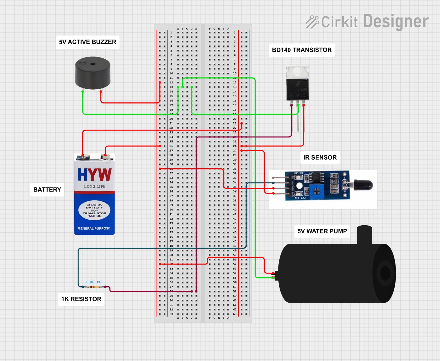
This circuit appears to be designed for a safety or monitoring system that detects heat or flames using a sensor and activates a buzzer and a water pump in response. The circuit is powered by a 9V battery and uses a TIP41C transistor as a switch to control the power to the buzzer and the water pump. A resistor is used to limit the current to the base of the transistor.
Component List
Heat Flame Sensor
- Pins: AO (Analog Output), DO (Digital Output), GND (Ground), VCC (Power Supply)
- Description: This sensor detects the presence of a flame or heat. The digital output (DO) can be used to trigger an alarm or activate a safety system.
Buzzer
- Pins: PIN (Signal Input), GND (Ground)
- Description: An audible alert device that is activated when a signal is applied to its input.
Water Pump
- Pins: Positive, Negative
- Description: A device that moves water when powered, possibly used for extinguishing detected flames.
TIP41C Transistor
- Pins: Base, Collector, Emitter
- Description: A power transistor that can switch larger currents, used to control the power to the buzzer and the water pump.
9V Battery
- Pins: + (Positive), - (Negative)
- Description: Provides the power supply for the circuit.
Resistor
- Pins: Pin1, Pin2
- Description: Limits the current flowing into the base of the TIP41C transistor.
- Properties: Resistance value of 1000 Ohms.
Comments
- Description: There are several comment components listed, but they do not have pins or properties associated with them. They may be used for annotation purposes in the circuit design.
Wiring Details
Heat Flame Sensor
- DO connected to one end of the Resistor.
- GND connected to the common ground net.
- VCC connected to the Emitter of the TIP41C transistor.
Buzzer
- PIN connected to the Collector of the TIP41C transistor.
- GND connected to the common ground net.
Water Pump
- Positive connected to the Collector of the TIP41C transistor.
- Negative connected to the common ground net.
TIP41C Transistor
- Base connected to the other end of the Resistor.
- Collector connected to the PIN of the Buzzer and the Positive of the Water Pump.
- Emitter connected to the VCC of the Heat Flame Sensor and the + of the 9V Battery.
9V Battery
- + connected to the Emitter of the TIP41C transistor.
- - connected to the common ground net.
Resistor
- Pin1 connected to the DO of the Heat Flame Sensor.
- Pin2 connected to the Base of the TIP41C transistor.
Documented Code
There is no code provided for any microcontrollers in this circuit. If the circuit is intended to be controlled by a microcontroller, the code would be necessary to define the behavior of the system, such as reading the sensor output and controlling the transistor to activate the buzzer and water pump. Since no code is provided, this section cannot be documented further.