Arduino Nano Gas Detection System with Wi-Fi and LED Indicators
Circuit Documentation
Summary
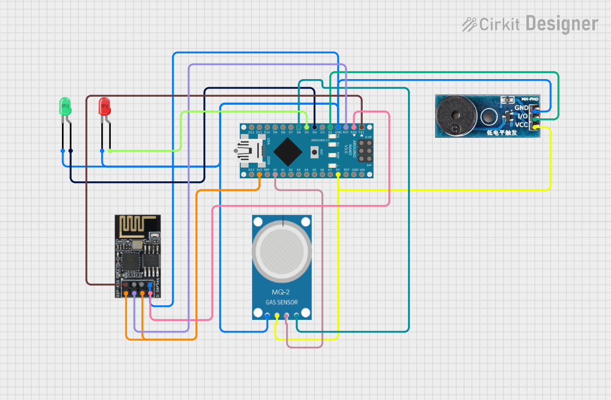
This document describes a circuit built using an Arduino Nano, a green LED, a red LED, a buzzer module, an MQ-2 gas sensor, and a WiFi module (ESP8266-01). The circuit is designed to monitor gas levels using the MQ-2 sensor and provide visual and auditory alerts when gas levels exceed a certain threshold. The green LED indicates normal operation, while the red LED and buzzer are activated when gas levels are high. The WiFi module is used for potential remote monitoring and control.
Component List
Arduino Nano
- Description: A small, complete, and breadboard-friendly board based on the ATmega328P.
- Pins: D1/TX, D0/RX, RESET, GND, D2, D3, D4, D5, D6, D7, D8, D9, D10, D11/MOSI, D12/MISO, VIN, 5V, A7, A6, A5, A4, A3, A2, A1, A0, AREF, 3V3, D13/SCK
LED: Two Pin (red)
- Description: A red LED with two pins: anode and cathode.
- Pins: cathode, anode
LED: Two Pin (green)
- Description: A green LED with two pins: anode and cathode.
- Pins: cathode, anode
Buzzer Module
- Description: A module that emits sound when activated.
- Pins: GND, Vcc, I/O
MQ-2 Gas Sensor
- Description: A sensor used to detect gas levels.
- Pins: GND, VCC, ANALOG, Digital
WiFi Module ESP8266-01
- Description: A WiFi module used for wireless communication.
- Pins: RX, GPIO0, GPIO2, GND, +3V3, Reset, CH-PD Chip power down, TX
Wiring Details
Arduino Nano
- D1/TX connected to RX of WiFi module ESP8266-01
- D0/RX connected to TX of WiFi module ESP8266-01
- RESET connected to Reset of WiFi module ESP8266-01
- GND connected to:
- GND of Buzzer Module
- GND of WiFi module ESP8266-01
- cathode of green LED
- cathode of red LED
- GND of MQ-2 Gas Sensor
- D2 connected to I/O of Buzzer Module
- D4 connected to anode of green LED
- D5 connected to anode of red LED
- D6 connected to Digital of MQ-2 Gas Sensor
- 5V connected to:
- Vcc of Buzzer Module
- VCC of MQ-2 Gas Sensor
- A0 connected to ANALOG of MQ-2 Gas Sensor
- 3V3 connected to:
- +3V3 of WiFi module ESP8266-01
- CH-PD Chip power down of WiFi module ESP8266-01
LED: Two Pin (red)
- cathode connected to GND of Arduino Nano
- anode connected to D5 of Arduino Nano
LED: Two Pin (green)
- cathode connected to GND of Arduino Nano
- anode connected to D4 of Arduino Nano
Buzzer Module
- GND connected to GND of Arduino Nano
- Vcc connected to 5V of Arduino Nano
- I/O connected to D2 of Arduino Nano
MQ-2 Gas Sensor
- GND connected to GND of Arduino Nano
- VCC connected to 5V of Arduino Nano
- ANALOG connected to A0 of Arduino Nano
- Digital connected to D6 of Arduino Nano
WiFi Module ESP8266-01
- RX connected to D1/TX of Arduino Nano
- TX connected to D0/RX of Arduino Nano
- Reset connected to RESET of Arduino Nano
- GND connected to GND of Arduino Nano
- +3V3 connected to 3V3 of Arduino Nano
- CH-PD Chip power down connected to 3V3 of Arduino Nano
Code Documentation
/*
 * Circuit Description:
 * This Arduino Nano circuit has a green LED connected to pin D4 and its cathode
 * connected to GND. The code ensures that the green LED is always on.
 * Additionally, a red LED is connected to pin D5 and its cathode connected to
 * GND. The code ensures that the red LED is always on.
 * A buzzer is connected to pin D2 and is always on.
 * An MQ-2 gas sensor is connected to analog pin A0 to read gas levels every 1 second.
 */

const int redLedPin = 5;     // Red LED connected to digital pin 5
const int greenLedPin = 4;   // Green LED connected to digital pin 4
const int buzzerPin = 2;     // Buzzer connected to digital pin 2
const int mq2AnalogPin = A0; // MQ-2 sensor connected to analog pin A0
const int threshold = 300;   // Threshold value for gas concentration

void setup() {
  pinMode(redLedPin, OUTPUT); // Set red LED pin as output
  pinMode(greenLedPin, OUTPUT); // Set green LED pin as output
  pinMode(buzzerPin, OUTPUT); // Set buzzer pin as output
  Serial.begin(9600); // Initialize serial communication
}

void loop() {

  int gasLevel = analogRead(mq2AnalogPin); // Read gas level from MQ-2 sensor
  Serial.print("Gas Level: ");
  Serial.println(gasLevel); // Print gas level to serial monitor

  if (gasLevel > threshold) { // If gas level exceeds threshold
    digitalWrite(buzzerPin, HIGH); // Turn on buzzer
    tone(buzzerPin, 1000, 1000);
    digitalWrite(redLedPin, HIGH); // Turn on red LED
    delay(1000); // Wait for 1 seconds
    noTone(buzzerPin); // Stop the buzzer tone
    digitalWrite(buzzerPin, LOW);  // Turn off buzzer
    digitalWrite(redLedPin, LOW);  // Turn off red LED
  } else {
    digitalWrite(greenLedPin, HIGH); // Turn on green LED
    delay(1000); // Green LED on for 2 second
    digitalWrite(greenLedPin, LOW);  // Turn off green LED
    delay(3000); // Wait for 3 seconds before next flash
  }
}
This code initializes the pins for the red LED, green LED, and buzzer as outputs. It reads the gas level from the MQ-2 sensor every second and prints the value to the serial monitor. If the gas level exceeds the threshold, the buzzer and red LED are activated. If the gas level is below the threshold, the green LED is flashed.