
Circuit Documentation
Summary
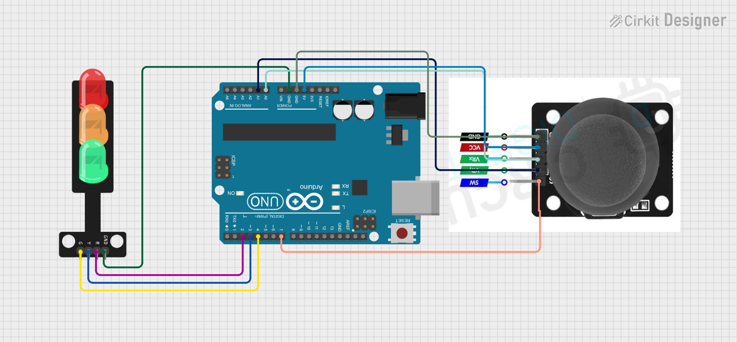
This circuit is designed to control a traffic light using an Arduino UNO and a joystick module. The traffic light has three LEDs (red, yellow, and green) that are controlled by the joystick's position. When the joystick is moved in different directions, the corresponding LED lights up on the traffic light. The joystick also has a built-in switch that can be used for additional input if needed.
Component List
Arduino UNO
- Description: A microcontroller board based on the ATmega328P.
- Pins Used:
5V,GND,A0,A1,D2,D3,D4,D7. - Purpose: Acts as the central controller for the circuit, reading inputs from the joystick and driving the traffic light LEDs.
Traffic Light
- Description: A simple traffic light module with three LEDs (green, yellow, red).
- Pins Used:
Green,Yellow,Red,GND. - Purpose: Provides visual output corresponding to the joystick's position.
Joystick Module
- Description: A module with a two-axis joystick and a pushbutton switch.
- Pins Used:
SW,VRY,VRX,VCC,GND. - Purpose: Serves as the user input device to control the traffic light LEDs.
Wiring Details
Arduino UNO
5Vto Joystick moduleVCCGNDto Joystick moduleGND, Traffic LightGNDA0to Joystick moduleVRXA1to Joystick moduleVRYD2to Traffic LightRedD3to Traffic LightYellowD4to Traffic LightGreenD7to Joystick moduleSW
Traffic Light
Greento Arduino UNOD4Yellowto Arduino UNOD3Redto Arduino UNOD2GNDto Arduino UNOGND
Joystick Module
VCCto Arduino UNO5VGNDto Arduino UNOGNDVRXto Arduino UNOA0VRYto Arduino UNOA1SWto Arduino UNOD7
Documented Code
/*
 * This Arduino sketch controls a traffic light using a joystick module.
 * When the joystick is moved up, the red LED turns on.
 * When the joystick is moved left, the yellow LED turns on.
 * When the joystick is moved right, the green LED turns on.
 * When the joystick is moved down, all LEDs turn on.
 */

const int redLED = 2;       // Connects to the red LED on the traffic light
const int yellowLED = 3;    // Connects to the yellow LED on the traffic light
const int greenLED = 4;     // Connects to the green LED on the traffic light
const int joystickSW = 7;   // Connects to the switch on the joystick
const int joystickVRX = A0; // Connects to the X-axis on the joystick
const int joystickVRY = A1; // Connects to the Y-axis on the joystick

void setup() {
  pinMode(redLED, OUTPUT);
  pinMode(yellowLED, OUTPUT);
  pinMode(greenLED, OUTPUT);
  pinMode(joystickSW, INPUT);
  Serial.begin(9600);
}

void loop() {
  int xValue = analogRead(joystickVRX);
  int yValue = analogRead(joystickVRY);
  Serial.print("X: ");
  Serial.print(xValue);
  Serial.print(" Y: ");
  Serial.println(yValue);

  if (yValue < 300) { // Joystick moved up
    digitalWrite(redLED, HIGH);
    digitalWrite(yellowLED, LOW);
    digitalWrite(greenLED, LOW);
  } else if (xValue < 300) { // Joystick moved left
    digitalWrite(redLED, LOW);
    digitalWrite(yellowLED, HIGH);
    digitalWrite(greenLED, LOW);
  } else if (xValue > 700) { // Joystick moved right
    digitalWrite(redLED, LOW);
    digitalWrite(yellowLED, LOW);
    digitalWrite(greenLED, HIGH);
  } else if (yValue > 700) { // Joystick moved down
    digitalWrite(redLED, HIGH);
    digitalWrite(yellowLED, HIGH);
    digitalWrite(greenLED, HIGH);
  } else { // Joystick in neutral position
    digitalWrite(redLED, LOW);
    digitalWrite(yellowLED, LOW);
    digitalWrite(greenLED, LOW);
  }
  delay(100);
}
This code is designed to be uploaded to the Arduino UNO microcontroller. It initializes the pins connected to the LEDs and joystick, reads the joystick's analog values, and controls the traffic light LEDs based on the joystick's position. Serial output is provided for debugging purposes.