
ESP32-Based Ultrasonic Measurement and Weight Monitoring System with LCD Feedback
View and Edit Project In Cirkit Designer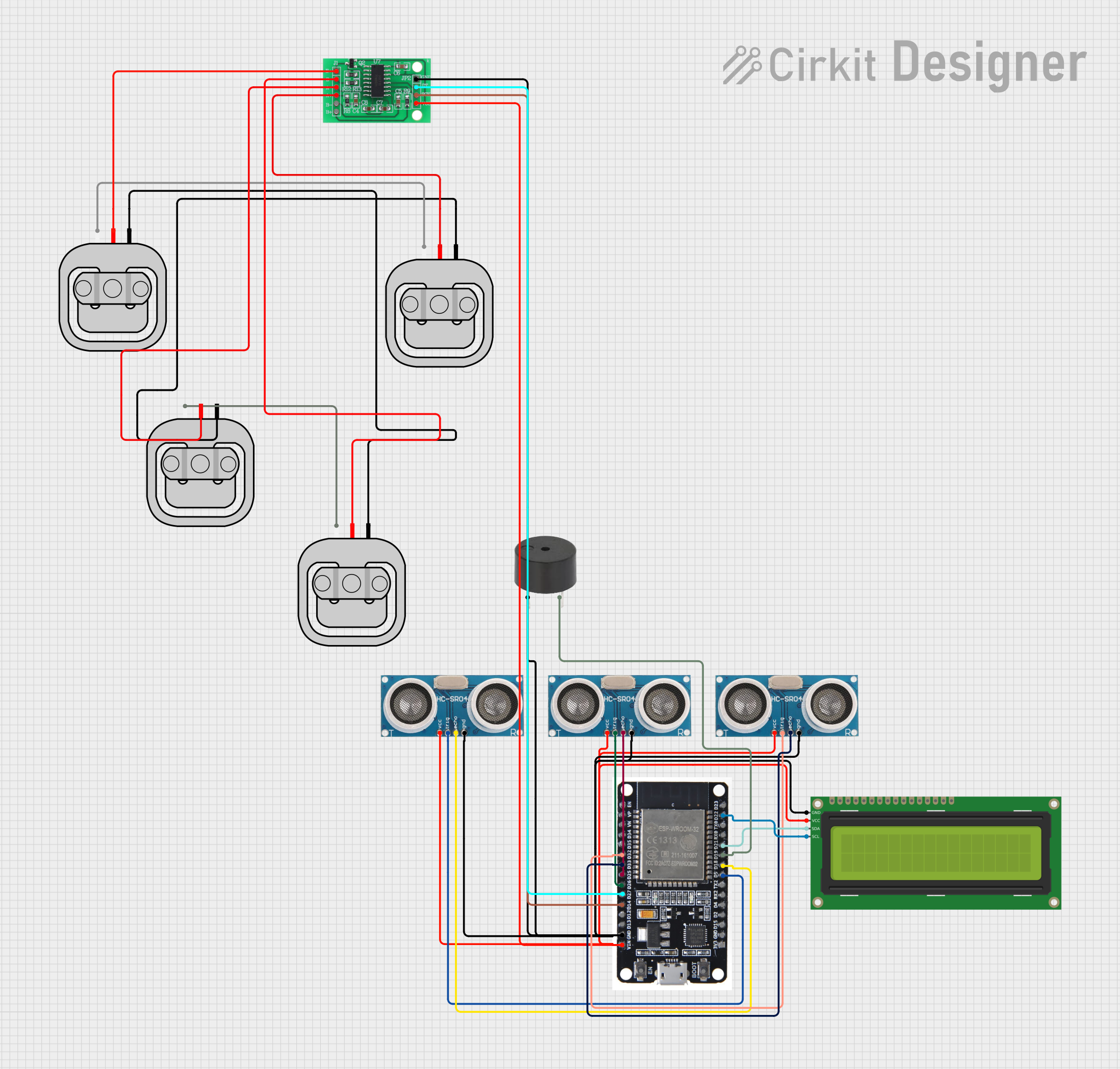
Circuit Documentation
Summary
The circuit in question appears to be a sensor-based system, likely used for measuring distances and weights, and providing feedback through a display and a buzzer. It includes multiple ultrasonic sensors for distance measurement, load sensors for weight measurement, an HX711 bridge sensor interface for load sensor signal conditioning, an ESP32 microcontroller for processing sensor data, a 16x2 I2C LCD for displaying information, and a buzzer for audible alerts.
Component List
Ultrasonic Sensor
- Description: A sensor that measures distance by emitting ultrasonic waves and measuring the time taken for the echo to return.
- Pins: +VCC, Trigger, Echo, GND
16x2 I2C LCD
- Description: A liquid crystal display that can show 16 characters per line with 2 lines, interfaced via the I2C protocol.
- Pins: GND, VCC, SDA, SCL
Buzzer
- Description: An electronic component that emits sound when powered.
- Pins: PIN, GND
Load Sensor - 50kg
- Description: A weight measurement sensor capable of measuring up to 50 kilograms.
- Pins: W, R, B
ESP32
- Description: A microcontroller with Wi-Fi and Bluetooth capabilities, suitable for a variety of applications in IoT.
- Pins: EN, VP, VN, D34, D35, D32, D33, D25, D26, D27, D14, D12, D13, GND, VIN, 3V3, D15, D2, D4, RX2, TX2, D5, D18, D19, D21, RX0, TX0, D22, D23, BOOT
HX711 - Bridge Sensor Interface
- Description: An ADC converter and signal amplifier for bridge sensors like load cells.
- Pins: E+, E-, A-, A+, B-, B+, GND - GROUND, DATA (OUT), SCK - CLOCK (IN), 3.3/3.5V Supply
Wiring Details
Ultrasonic Sensor
- VCC: Connected to the power supply (VIN) of the ESP32.
- Trigger: Connected to a GPIO pin on the ESP32 for initiating distance measurement.
- Echo: Connected to a GPIO pin on the ESP32 for receiving the echo signal.
- GND: Common ground with the ESP32 and other components.
16x2 I2C LCD
- GND: Common ground with the ESP32 and other components.
- VCC: Connected to the power supply (VIN) of the ESP32.
- SDA: Connected to the I2C data line (D21) on the ESP32.
- SCL: Connected to the I2C clock line (D22) on the ESP32.
Buzzer
- PIN: Connected to a GPIO pin on the ESP32 for control.
- GND: Common ground with the ESP32 and other components.
Load Sensor - 50kg
- W: Wired together for multiple load sensors.
- R: Connected to the HX711 for signal reading.
- B: Wired together for multiple load sensors.
ESP32
- Various GPIO Pins: Connected to the Trigger and Echo pins of the Ultrasonic Sensors, the SDA and SCL pins of the I2C LCD, the control pin of the Buzzer, and the DATA and SCK pins of the HX711.
- GND: Common ground with all components.
- VIN: Power supply input connected to the VCC of other components.
HX711 - Bridge Sensor Interface
- E+, E-: Excitation voltage pins for the load sensors.
- A-, A+: Input pins for the load sensor signals.
- B-, B+: Additional input pins for bridge sensors (not used in this circuit).
- GND - GROUND: Common ground with the ESP32 and other components.
- DATA (OUT): Connected to a GPIO pin on the ESP32 for data output.
- SCK - CLOCK (IN): Connected to a GPIO pin on the ESP32 for clock input.
- 3.3/3.5V Supply: Connected to the power supply (VIN) of the ESP32.
Documented Code
The provided code list is empty, indicating that there is no embedded code available for the microcontroller at this time. When the code becomes available, it should be documented here with explanations for each function and routine, detailing how the ESP32 interacts with the sensors and other components in the circuit.