Cirkit Designer
Your all-in-one circuit design IDE
Home /
Project Documentation
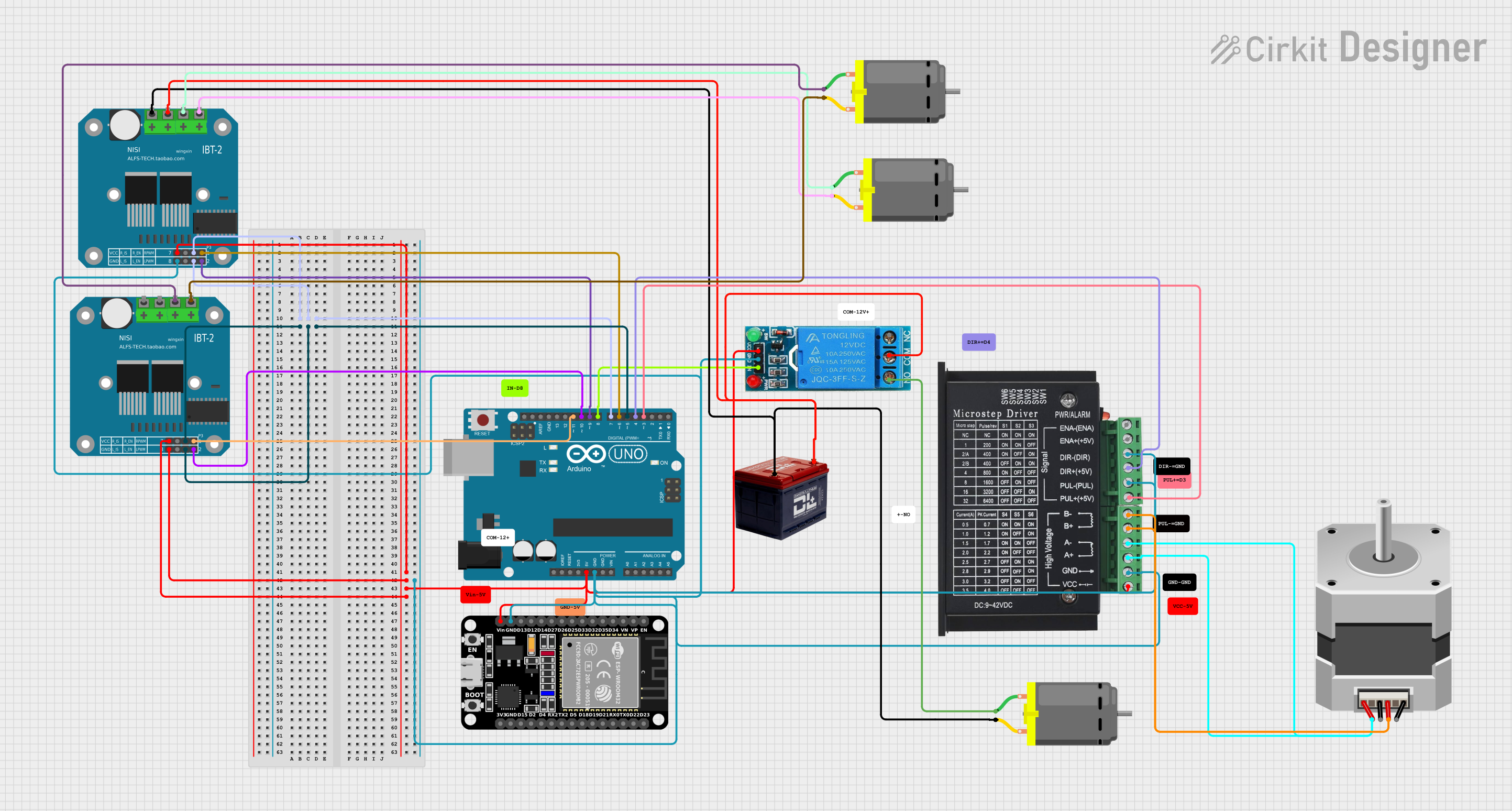
Arduino and ESP32 Controlled Motor System with Relay and BTS7960 Drivers
Circuit Documentation
Summary
This circuit involves an Arduino UNO, an ESP32, a 12V single-channel relay, a TB6600 micro-stepping motor driver, a BTS7960 motor driver, a 12V battery, a DC motor, and a bipolar stepper motor. The Arduino UNO is the primary microcontroller, controlling the relay and motor drivers to manage the DC motor and stepper motor. The ESP32 is also included in the circuit, potentially for additional control or communication purposes.
Component List
Arduino UNO
- Description: A microcontroller board based on the ATmega328P.
- Pins: UNUSED, IOREF, Reset, 3.3V, 5V, GND, Vin, A0, A1, A2, A3, A4, A5, SCL, SDA, AREF, D13, D12, D11, D10, D9, D8, D7, D6, D5, D4, D3, D2, D1, D0
ESP32 (30 pin)
- Description: A low-cost, low-power system on a chip microcontroller with integrated Wi-Fi and dual-mode Bluetooth.
- Pins: EN, VP, VN, D34, D35, D32, D33, D25, D26, D27, D14, D12, D13, GND, Vin, D23, D22, TX0, RX0, D21, D19, D18, D5, TX2, RX2, D4, D2, D15, 3V3
12V SINGLE CHANNEL RELAY
- Description: A relay module that allows a microcontroller to control high voltage devices.
- Pins: NC, COM, NO, IN, GND, VCC
TB6600 Micro Stepping Motor Driver
- Description: A stepper motor driver capable of driving bipolar stepper motors.
- Pins: ENA-, ENA+, DIR-, DIR+, PUL-, PUL+, B-, B+, A-, A+, GND, VCC
BTS7960 Motor Driver
- Description: A high-power motor driver module.
- Pins: Pin 1, Pin 2, Pin 3, Pin 4, Pin 5, Pin 6, Pin 7, Pin 8, Pin 9, Pin 10, Pin 11, Pin 12
Battery 12V
- Description: A 12V battery used to power the circuit.
- Pins: -, +
DC Motor
- Description: A simple DC motor.
- Pins: pin 1, pin 2
Stepper Motor (Bipolar)
- Description: A bipolar stepper motor.
- Pins: D, B, C, A
Wiring Details
Arduino UNO
- 5V connected to VCC of 12V SINGLE CHANNEL RELAY, TB6600 Micro Stepping Motor Driver, Vin of ESP32, Pin 5 of BTS7960 Motor Driver, Pin 1 and Pin 5 of another BTS7960 Motor Driver.
- GND connected to GND of 12V SINGLE CHANNEL RELAY, TB6600 Micro Stepping Motor Driver, DIR- and PUL- of TB6600 Micro Stepping Motor Driver, GND of ESP32, Pin 1 of BTS7960 Motor Driver.
- D11 connected to Pin 8 of BTS7960 Motor Driver.
- D10 connected to Pin 4 of BTS7960 Motor Driver.
- D9 connected to Pin 4 of another BTS7960 Motor Driver.
- D8 connected to IN of 12V SINGLE CHANNEL RELAY.
- D7 connected to Pin 3 and Pin 7 of BTS7960 Motor Driver.
- D6 connected to Pin 8 of another BTS7960 Motor Driver.
- D5 connected to Pin 3 and Pin 7 of another BTS7960 Motor Driver.
- D4 connected to DIR+ of TB6600 Micro Stepping Motor Driver.
- D3 connected to PUL+ of TB6600 Micro Stepping Motor Driver.
ESP32 (30 pin)
- Vin connected to 5V of Arduino UNO.
- GND connected to GND of Arduino UNO.
12V SINGLE CHANNEL RELAY
- VCC connected to 5V of Arduino UNO.
- GND connected to GND of Arduino UNO.
- IN connected to D8 of Arduino UNO.
- COM connected to + of Battery 12V and Pin 11 of BTS7960 Motor Driver.
- NO connected to pin 1 of DC Motor.
TB6600 Micro Stepping Motor Driver
- VCC connected to 5V of Arduino UNO.
- GND connected to GND of Arduino UNO.
- DIR- connected to GND of Arduino UNO.
- PUL- connected to GND of Arduino UNO.
- DIR+ connected to D4 of Arduino UNO.
- PUL+ connected to D3 of Arduino UNO.
- B- and B+ connected to B of Stepper Motor.
- A- and A+ connected to A of Stepper Motor.
BTS7960 Motor Driver
- Pin 1 connected to 5V of Arduino UNO.
- Pin 3 connected to D7 of Arduino UNO.
- Pin 4 connected to D10 of Arduino UNO.
- Pin 5 connected to 5V of Arduino UNO.
- Pin 7 connected to D7 of Arduino UNO.
- Pin 8 connected to D11 of Arduino UNO.
- Pin 9 connected to pin 2 of DC Motor.
- Pin 10 connected to pin 1 of DC Motor.
- Pin 11 connected to COM of 12V SINGLE CHANNEL RELAY.
- Pin 12 connected to - of Battery 12V.
Battery 12V
- + connected to COM of 12V SINGLE CHANNEL RELAY and Pin 11 of BTS7960 Motor Driver.
- - connected to Pin 12 of BTS7960 Motor Driver and pin 2 of DC Motor.
DC Motor
- pin 1 connected to NO of 12V SINGLE CHANNEL RELAY.
- pin 2 connected to - of Battery 12V.
Stepper Motor (Bipolar)
- B connected to B- and B+ of TB6600 Micro Stepping Motor Driver.
- A connected to A- and A+ of TB6600 Micro Stepping Motor Driver.
Documented Code
int relayPin = 8;  // Pin connected to the relay
int motorEnablePin = 7;  // Pin connected to BTS7960 Pin 3 and Pin 7
int motorDirectionPin = 6;  // Pin connected to BTS7960 Pin 8
int motorPWM = 9;  // Pin connected to BTS7960 Pin 4

void setup() {
  // Set the relay pin as an output
  pinMode(relayPin, OUTPUT);

  // Set the motor control pins as outputs
  pinMode(motorEnablePin, OUTPUT);
  pinMode(motorDirectionPin, OUTPUT);
  pinMode(motorPWM, OUTPUT);
}

void loop() {
  // Control the relay to turn the DC motor on and off
  digitalWrite(relayPin, HIGH);  // Turn on the relay (and the motor)
  delay(2000);  // Wait for 2 seconds
  digitalWrite(relayPin, LOW);  // Turn off the relay (and the motor)
  delay(2000);  // Wait for 2 seconds

  // Control the BTS7960 motor driver
  digitalWrite(motorEnablePin, HIGH);  // Enable the motor driver
  digitalWrite(motorDirectionPin, HIGH);  // Set motor direction
  analogWrite(motorPWM, 128);  // Set motor speed (0-255)
  delay(2000);  // Run the motor for 2 seconds

  digitalWrite(motorDirectionPin, LOW);  // Change motor direction
  analogWrite(motorPWM, 128);  // Set motor speed (0-255)
  delay(2000);  // Run the motor for 2 seconds

  digitalWrite(motorEnablePin, LOW);  // Disable the motor driver
  delay(2000);  // Wait for 2 seconds
}
This code is for the Arduino UNO and controls the relay and BTS7960 motor driver to manage the DC motor. The relay is toggled on and off every 2 seconds, and the motor driver is used to control the motor's direction and speed.