
Arduino UNO Weather Station with Rain Detection and Servo Control
View and Edit Project In Cirkit Designer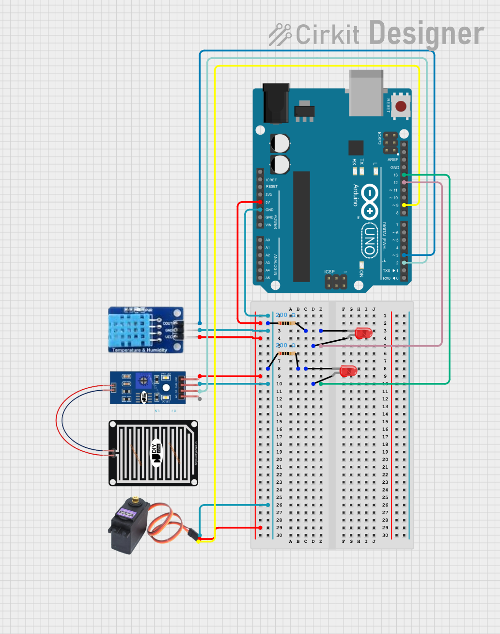
Circuit Documentation
Summary
This circuit is designed to interface with various sensors and actuators using an Arduino UNO microcontroller. It includes a rain sensor for detecting water presence, a DHT11 sensor for measuring temperature and humidity, and a servo motor (MG996R) for actuation. Additionally, the circuit incorporates two red LEDs, each with a corresponding resistor to limit the current. The Arduino UNO serves as the central processing unit, controlling the sensors and actuators based on the programmed logic.
Component List
RAIN SENSOR
- Pins: AO (Analog Output), DO (Digital Output), GRD (Ground), VCC (Power Supply)
- Description: Detects the presence of rain or water.
Arduino UNO
- Pins: UNUSED, IOREF, Reset, 3.3V, 5V, GND, Vin, A0-A5, SCL, SDA, AREF, D13-D0
- Description: Microcontroller board based on the ATmega328P, used for controlling the sensors and actuators in the circuit.
LED: Two Pin (red)
- Pins: cathode, anode
- Description: Emits red light when powered.
Resistor
- Pins: pin1, pin2
- Properties: Resistance: 200 Ohms
- Description: Limits the current flowing through the LEDs to prevent damage.
DHT11
- Pins: DATA, GND, VCC
- Description: Measures ambient temperature and humidity.
MG996R
- Pins: GND, VCC, SIG
- Description: Servo motor used for precise angular movement.
Wiring Details
RAIN SENSOR
- Digital Output (DO): Connected to Arduino UNO pin D2.
- Ground (GRD): Connected to common ground.
- Power Supply (VCC): Connected to Arduino UNO 5V output.
Arduino UNO
- Digital Pins (D12, D13): Connected to the anodes of two red LEDs.
- Ground (GND): Connected to common ground.
- 5V Output: Powers the RAIN SENSOR, DHT11, and MG996R.
- Digital Pin (D9): Sends control signal to MG996R servo motor.
- Digital Pin (D3): Receives data from DHT11 sensor.
- Digital Pin (D2): Receives digital output from RAIN SENSOR.
LED: Two Pin (red)
- Anode: Connected to Arduino UNO digital pins D12 and D13 (one LED per pin).
- Cathode: Connected to one end of a 200 Ohm resistor.
Resistor
- Pin1: Connected to common ground.
- Pin2: Connected to the cathode of a red LED.
DHT11
- Data (DATA): Connected to Arduino UNO pin D3.
- Ground (GND): Connected to common ground.
- Power Supply (VCC): Connected to Arduino UNO 5V output.
MG996R
- Signal (SIG): Connected to Arduino UNO pin D9.
- Ground (GND): Connected to common ground.
- Power Supply (VCC): Connected to Arduino UNO 5V output.
Documented Code
Arduino UNO Code (sketch.ino)
void setup() {
  // put your setup code here, to run once:

}

void loop() {
  // put your main code here, to run repeatedly:

}
Additional Notes (documentation.txt)
No additional code documentation provided.