
Circuit Documentation
Summary
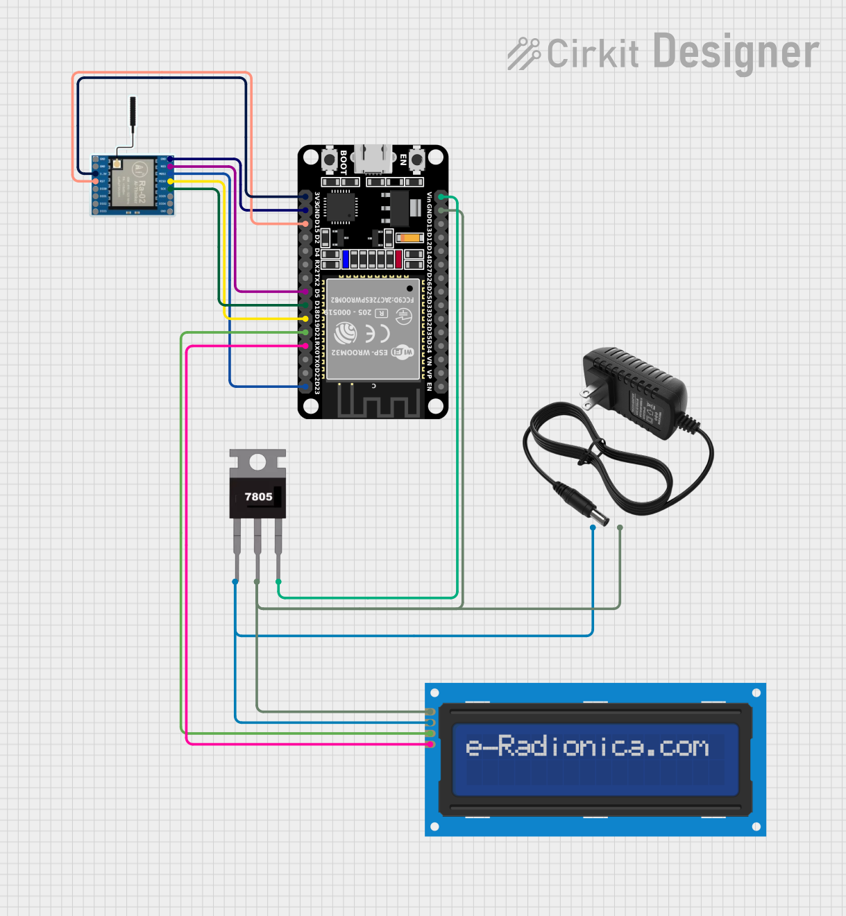
This circuit integrates an ESP32 microcontroller with a LoRa Ra-02 SX1278 module for wireless communication, an LCD screen for display purposes, and a 7805 voltage regulator to step down the voltage from a 12V power supply to a stable 5V required by the ESP32 and other components. The ESP32 serves as the central processing unit, interfacing with the LoRa module for long-range communication and the LCD screen for user interaction. The 7805 regulator ensures that the components receive a safe and stable voltage from the 12V power supply.
Component List
ESP32 (30 pin)
- Description: A powerful microcontroller with Wi-Fi and Bluetooth capabilities.
- Pins: EN, VP, VN, D34, D35, D32, D33, D25, D26, D27, D14, D12, D13, GND, Vin, D23, D22, TX0, RX0, D21, D19, D18, D5, TX2, RX2, D4, D2, D15, 3V3
LoRa Ra-02 SX1278
- Description: A long-range wireless communication module based on the SX1278 chip.
- Pins: GND, NSS, MOSI, MISO, SCK, D105, DI04, 3.3V, RST, DI00, DI01, D102, DI03
7805 Voltage Regulator
- Description: A voltage regulator that outputs a stable 5V from a higher voltage input.
- Pins: Vin, Gnd, Vout
12V Power Supply
- Description: Provides a 12V voltage source for the circuit.
- Pins: +, -
LCD Screen 16x2 I2C
- Description: A 16x2 character LCD display with an I2C interface.
- Pins: SCL, SDA, VCC, GND
Wiring Details
ESP32 (30 pin)
- GND connected to the ground net of the circuit.
- Vin connected to the 5V output from the 7805 voltage regulator.
- D23 (MOSI) connected to the LoRa module's MOSI pin.
- RX0 connected to the LCD screen's SCL pin.
- D21 (SDA) connected to the LCD screen's SDA pin.
- D19 (MISO) connected to the LoRa module's MISO pin.
- D18 (SCK) connected to the LoRa module's SCK pin.
- D5 (NSS) connected to the LoRa module's NSS pin.
- D15 (RST) connected to the LoRa module's RST pin.
- 3V3 connected to the LoRa module's 3.3V pin.
LoRa Ra-02 SX1278
- GND connected to the ground net of the circuit.
- NSS connected to ESP32's D5 pin.
- MOSI connected to ESP32's D23 pin.
- MISO connected to ESP32's D19 pin.
- SCK connected to ESP32's D18 pin.
- RST connected to ESP32's D15 pin.
- 3.3V connected to ESP32's 3V3 pin.
7805 Voltage Regulator
- Vin connected to the 12V power supply's positive output.
- Gnd connected to the ground net of the circuit.
- Vout connected to ESP32's Vin pin and indirectly to the LCD screen's VCC pin.
12V Power Supply
-
- connected to the 7805 voltage regulator's Vin pin and indirectly to the LCD screen's VCC pin.
-
- connected to the ground net of the circuit.
LCD Screen 16x2 I2C
- SCL connected to ESP32's RX0 pin.
- SDA connected to ESP32's D21 pin.
- VCC connected to the 12V power supply through the 7805 voltage regulator.
- GND connected to the ground net of the circuit.
Documented Code
No code has been provided for the microcontrollers in the circuit. When code is available, it should be documented here with explanations for each function and routine, including setup and loop functions, interrupt service routines, and any libraries or external modules used.