
Arduino Nano-Controlled Robotics Interface with I2C Servo Driver and Wireless Communication
View and Edit Project In Cirkit Designer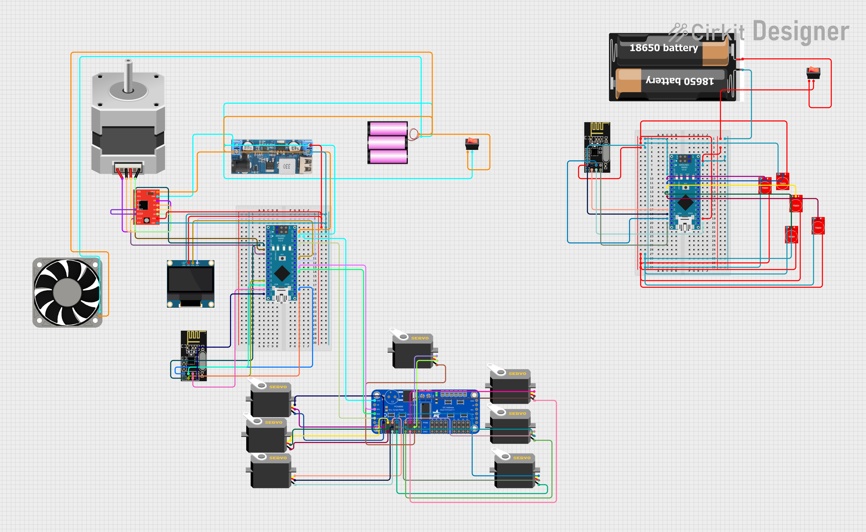
Circuit Documentation
Summary
This circuit is designed to control a variety of components including servos, a stepper motor, an OLED display, touch sensors, and wireless communication modules. It is powered by a 12V battery and includes a step-down converter to provide 5V where needed. The circuit is controlled by two Arduino Nano microcontrollers, which interface with an Adafruit 16-Channel PWM Servo Driver for servo control, an A4988 Stepper Motor Driver for the stepper motor, and NRF24L01 modules for wireless communication. Touch sensors provide user input, and a small OLED display offers a visual interface. Rocker switches are used to control power to the system.
Component List
- Adafruit 16-Channel 12-bit PWM Servo Driver - I2C: Used to control up to 16 servos with I2C communication.
- Arduino Nano: The main microcontroller used for processing and controlling the various components in the circuit.
- Touch Sensor TTP233: Capacitive touch sensors used for user input.
- Servo: Actuators that can be positioned to specific angles using PWM signals.
- 0.96" OLED: A small display for showing information or status.
- Stepper Motor (Bipolar): A motor that moves in discrete steps, used for precise control of motion.
- Battery 12V: The primary power source for the circuit.
- 12V to 5V Step Down Power Converter: Converts the 12V supply to 5V for components requiring lower voltage.
- 40mm Fan 12V: Provides cooling to the system.
- NRF24L01: Wireless communication modules for remote control or data transmission.
- 2x 18650 Batteries: Secondary power source for parts of the circuit.
- A4988 Stepper Motor Driver (Red): Controls the bipolar stepper motor.
- Rocker Switch: Used to turn the power supply on and off.
Wiring Details
Adafruit 16-Channel 12-bit PWM Servo Driver - I2C
- 5.0V: Connected to the 5V output from the step-down converter.
- VCC: Connected to the 5V pin on the Arduino Nano.
- SDA: Connected to the A2 pin on the Arduino Nano.
- SCL: Connected to the A3 pin on the Arduino Nano.
- OE: Not connected.
- GND: Connected to the ground plane.
- PWM0 - PWM15: Connected to the pulse pins of the respective servos.
Arduino Nano
- VIN: Connected to the 12V battery through a rocker switch.
- GND: Connected to the ground plane.
- D2 - D13: Various connections to stepper motor driver, OLED display, NRF24L01 module, and touch sensors.
- A0 - A7: Used for I2C communication and other sensor inputs.
- 5V: Provides power to the PWM Servo Driver and other 5V components.
- 3V3: Provides power to the NRF24L01 modules and touch sensors.
Touch Sensor TTP233
- GND: Connected to the ground plane.
- I/O: Connected to digital pins on the Arduino Nano (D2, D3, D4, D5, D6).
- VCC: Connected to the 3.3V output from the Arduino Nano.
Servo
- GND: Connected to the ground plane.
- VCC: Connected to the 5V output from the PWM Servo Driver.
- Pulse: Connected to the PWM outputs on the PWM Servo Driver.
0.96" OLED
- GND: Connected to the ground plane.
- VDD: Connected to the 5V output from the step-down converter.
- SCK: Connected to the A5 pin on the Arduino Nano.
- SDA: Connected to the A4 pin on the Arduino Nano.
Stepper Motor (Bipolar)
- D, B, C, A: Connected to the respective outputs on the A4988 Stepper Motor Driver.
Battery 12V
- +: Connected to the VIN+ on the step-down converter and the input of the rocker switch.
- -: Connected to the ground plane.
12V to 5V Step Down Power Converter
- VIN 9V-36V: Not connected.
- VIN+: Connected to the +12V from the battery.
- VIN-: Connected to the ground plane.
- USB OUTPUT 5V: Not connected.
- 5V OUTPUT: Provides 5V to the OLED display and the A4988 Stepper Motor Driver.
- GND: Connected to the ground plane.
40mm Fan 12V
- +12V: Connected to the 12V battery through a rocker switch.
- -12V: Connected to the ground plane.
NRF24L01
- IRQ (not used): Not connected.
- MOSI: Connected to the D11/MOSI pin on the Arduino Nano.
- CSN: Connected to the D10 pin on the Arduino Nano.
- VCC (3V): Connected to the 3.3V output from the Arduino Nano.
- GND: Connected to the ground plane.
- CE: Connected to the D9 pin on the Arduino Nano.
- SCK: Connected to the D13/SCK pin on the Arduino Nano.
- MISO: Connected to the D12/MISO pin on the Arduino Nano.
A4988 Stepper Motor Driver (Red)
- ENABLE: Connected to the GND to keep the driver enabled.
- MS1, MS2, MS3: Not connected (full step mode).
- RESET: Connected to the SLEEP pin for normal operation.
- SLEEP: Connected to the RESET pin for normal operation.
- STEP: Connected to the D3 pin on the Arduino Nano.
- DIR: Connected to the D2 pin on the Arduino Nano.
- VMOT: Connected to the 12V battery.
- GND: Connected to the ground plane.
- 2B, 2A, 1A, 1B: Connected to the respective wires of the bipolar stepper motor.
- VDD: Connected to the 5V output from the step-down converter.
Rocker Switch
- Output: Connected to the VIN pin on the Arduino Nano and the +12V on the fan.
- Input: Connected to the +12V from the battery.
Documented Code
Arduino Nano (Primary Controller)
void setup() {
  // put your setup code here, to run once:

}

void loop() {
  // put your main code here, to run repeatedly:

}
Arduino Nano (Secondary Controller)
void setup() {
  // put your setup code here, to run once:

}

void loop() {
  // put your main code here, to run repeatedly:

}
Note: The actual functionality of the code is not provided in the input and would typically include initialization of I2C, PWM, and other peripherals, as well as the main control logic for the circuit's operation.