
ESP32-Based Smart Irrigation System with Soil Moisture Sensing and IR Control
View and Edit Project In Cirkit Designer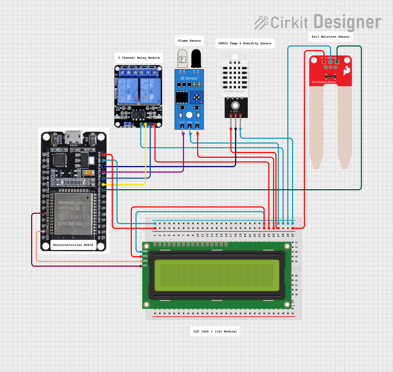
Circuit Documentation
Summary
The circuit in question appears to be a microcontroller-based system designed for environmental monitoring and control. The central processing unit of the circuit is an ESP32 microcontroller, which is responsible for interfacing with various sensors and an output device. The sensors include an IR sensor, a DHT22 temperature and humidity sensor, and a SparkFun Soil Moisture Sensor. The output devices include a two-channel 5V relay and an I2C LCD 16x2 screen. The ESP32 is powered by a common power supply that also powers the sensors and the LCD screen. The relay module has separate power inputs but shares a common ground with the ESP32 and other components. The ESP32 reads sensor data and controls the relay based on programmed logic, which could be used for applications like automated watering systems or climate control.
Component List
ESP32
- Description: A microcontroller with Wi-Fi and Bluetooth capabilities, featuring a wide range of GPIO pins for interfacing with various peripherals.
- Pins: EN, VP, VN, D34, D35, D32, D33, D25, D26, D27, D14, D12, D13, GND, VIN, 3V3, D15, D2, D4, RX2, TX2, D5, D18, D19, D21, RX0, TX0, D22, D23, BOOT
Two Channel Relay 5V
- Description: A relay module with two channels that can be used to control high power devices such as motors or lights.
- Pins: VCC, IN2, IN1, GND, NC2, C2, NO2, NC1, C1, NO1
IR Sensor
- Description: An infrared sensor used for detecting obstacles or for simple communication.
- Pins: out, gnd, vcc
DHT22
- Description: A sensor for measuring temperature and humidity in the environment.
- Pins: +, Out, -
SparkFun Soil Moisture Sensor
- Description: A sensor used to measure the moisture level in the soil, which can be useful in gardening or agriculture applications.
- Pins: VCC, GND, SIG
I2C LCD 16x2 Screen
- Description: A liquid crystal display that can show text or numbers, interfaced via the I2C protocol.
- Pins: SCL, SDA, VCC (5V), GND, VDD, VO, RS, RW, E, D0, D1, D2, D3, D4, D5, D6, D7, BLA, BLK
Wiring Details
ESP32
- VIN connected to the common power supply.
- GND connected to the common ground.
- D26 connected to the SIG pin of the SparkFun Soil Moisture Sensor.
- D27 connected to the IN1 pin of the Two Channel Relay 5V.
- D14 connected to the IN2 pin of the Two Channel Relay 5V.
- D12 connected to the out pin of the IR Sensor.
- D13 connected to the Out pin of the DHT22.
- D21 (SCL) connected to the SCL pin of the I2C LCD 16x2 Screen.
- D22 (SDA) connected to the SDA pin of the I2C LCD 16x2 Screen.
Two Channel Relay 5V
- VCC connected to the common power supply.
- GND connected to the common ground.
- IN1 controlled by ESP32 pin D27.
- IN2 controlled by ESP32 pin D14.
IR Sensor
- vcc connected to the common power supply.
- gnd connected to the common ground.
- out connected to ESP32 pin D12.
DHT22
-
- connected to the common power supply.
-
- connected to the common ground.
- Out connected to ESP32 pin D13.
SparkFun Soil Moisture Sensor
- VCC connected to the common power supply.
- GND connected to the common ground.
- SIG connected to ESP32 pin D26.
I2C LCD 16x2 Screen
- VCC (5V) connected to the common power supply.
- GND connected to the common ground.
- SCL connected to ESP32 pin D21.
- SDA connected to ESP32 pin D22.
Documented Code
No code was provided for the microcontroller. Typically, the code would be responsible for initializing the peripherals, reading sensor data, processing the data, and controlling the output devices based on the logic defined for the application. The code would also handle communication protocols such as I2C for the LCD screen. Without the code, we cannot document the specific functionalities or the logic implemented in the circuit.