
Arduino UNO Based Environmental Monitoring System with GSM Reporting
View and Edit Project In Cirkit Designer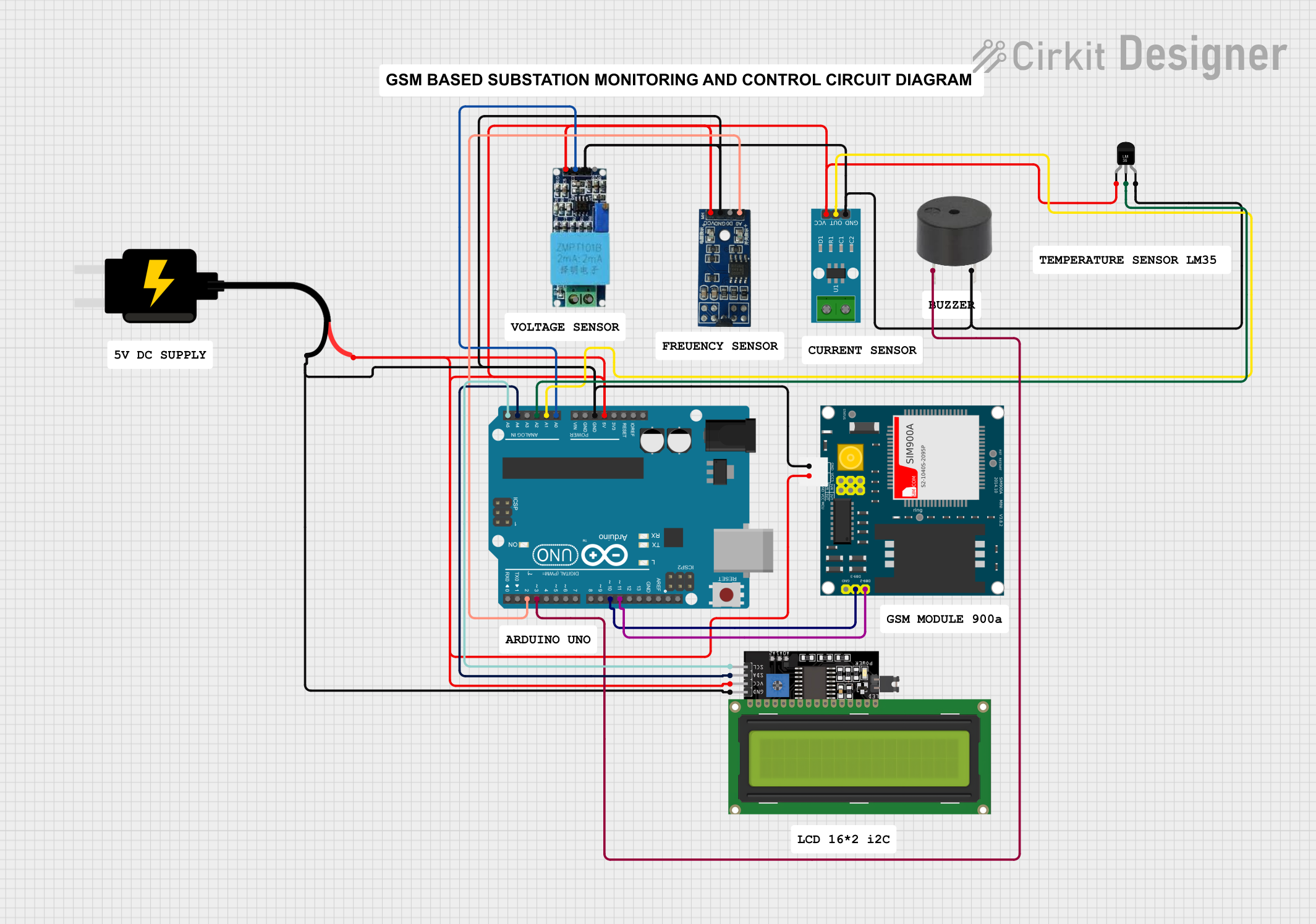
Circuit Documentation
Summary
This circuit integrates various sensors, a microcontroller, a display, and a communication module to perform a series of measurements and interactions. The core of the circuit is an Arduino UNO, which is responsible for controlling the sensors, processing the data, and managing the communication with the SIM900A GSM module. The circuit is powered by a 5V DC source, ensuring all components receive the necessary voltage. The sensors include a temperature sensor (LM35), a voltage sensor, an ACS712 current sensor, and a Hall effect sensor. An LCD display with I2C interface is used to show information, and a buzzer is included for audible alerts.
Component List
- Arduino UNO: A microcontroller board based on the ATmega328P, featuring digital and analog I/O pins.
- Buzzer: An electromechanical component that produces sound when energized.
- Temperature Sensor (LM35): A precision integrated-circuit temperature sensor with an analog output voltage linearly proportional to the Centigrade temperature.
- LCD Display 16x4 I2C: A liquid crystal display with 16 characters per line and 4 lines, featuring an I2C interface for communication.
- DC Source 5V: A power supply module that provides a regulated 5V output.
- Voltage Sensor: A module designed to measure the voltage in a circuit.
- ACS712 Current Sensor 5A 20A 30A: A hall-effect-based linear current sensor with an analog output, capable of measuring both AC and DC currents.
- Hall sensor (magnetic): A sensor that detects magnetic fields and outputs a voltage corresponding to the magnetic field strength.
- SIM900A: A GSM/GPRS module that allows for cellular communication, including SMS and voice calls.
Wiring Details
Arduino UNO
- 5V: Connected to the 5V power rail.
- GND: Connected to the ground rail.
- A0: Connected to the output of the Voltage Sensor.
- A1: Connected to the output of the ACS712 Current Sensor.
- A2: Connected to the Vout of the Temperature Sensor (LM35).
- A4 (SDA): Connected to the SDA pin of the LCD Display.
- A5 (SCL): Connected to the SCL pin of the LCD Display.
- D2: Connected to the A0 (Analog) pin of the Hall sensor (magnetic).
- D3: Connected to the PIN of the buzzer.
- D10: Connected to the DB9-3 (RXD) of the SIM900A.
- D11: Connected to the DB9-2 (TXD) of the SIM900A.
Buzzer
- PIN: Connected to D3 on the Arduino UNO.
- GND: Connected to the ground rail.
Temperature Sensor (LM35)
- +Vs: Connected to the 5V power rail.
- Vout: Connected to A2 on the Arduino UNO.
- GND: Connected to the ground rail.
LCD Display 16x4 I2C
- SCL: Connected to A5 on the Arduino UNO.
- SDA: Connected to A4 on the Arduino UNO.
- VCC: Connected to the 5V power rail.
- GND: Connected to the ground rail.
DC Source 5V
- VCC: Connected to the 5V power rail.
- GND: Connected to the ground rail.
Voltage Sensor
- Vcc: Connected to the 5V power rail.
- Out: Connected to A0 on the Arduino UNO.
- Gnd: Connected to the ground rail.
ACS712 Current Sensor
- VCC: Connected to the 5V power rail.
- OUT: Connected to A1 on the Arduino UNO.
- GND: Connected to the ground rail.
Hall sensor (magnetic)
- VCC (5V): Connected to the 5V power rail.
- GND: Connected to the ground rail.
- A0 (Analog): Connected to D2 on the Arduino UNO.
SIM900A
- 5V: Connected to the 5V power rail.
- GND: Connected to the ground rail.
- DB9-2 (TXD): Connected to D11 on the Arduino UNO.
- DB9-3 (RXD): Connected to D10 on the Arduino UNO.
Documented Code
Arduino UNO Code (sketch.ino)
void setup() {
  // put your setup code here, to run once:

}

void loop() {
  // put your main code here, to run repeatedly:

}
Note: The provided code is a template and does not include specific functionality. It should be populated with the logic required to read sensors, control outputs, and communicate with the SIM900A module.