
ESP8266 Controlled Robotics Platform with GPS, IR, and GSM Features
View and Edit Project In Cirkit Designer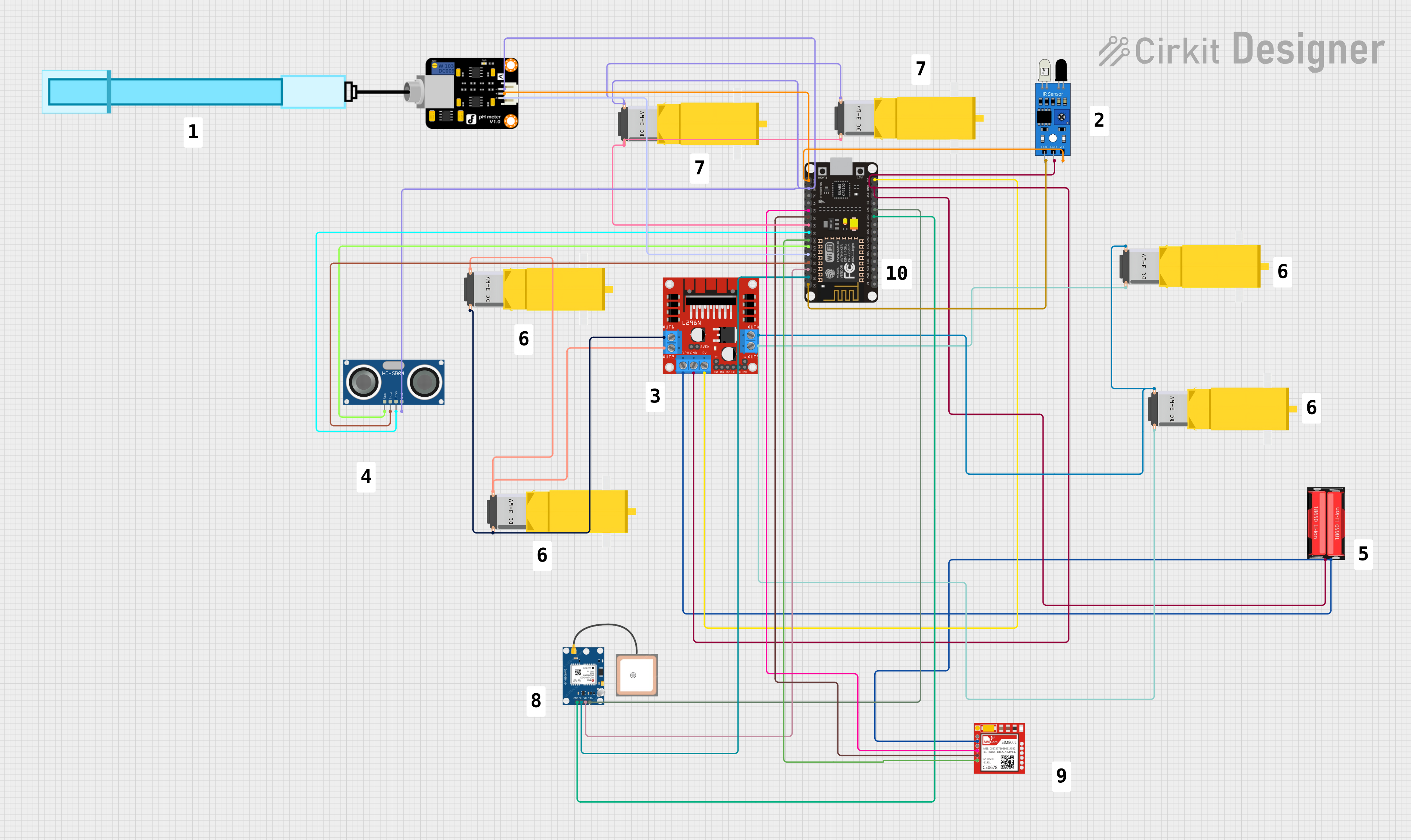
Circuit Documentation
Summary
This circuit integrates various components including sensors, a microcontroller, a motor driver, and a power source to create a multifunctional system. The core of the circuit is an ESP8266 NodeMCU microcontroller, which interfaces with an IR sensor, a GPS module, an ultrasonic sensor, a pH meter, a SIM800L GSM module, and multiple gearmotors through an L298N motor driver. The circuit is powered by an 18650 Li-Ion battery. The ESP8266 NodeMCU is programmed to control and interact with these components, likely for a robotics or remote monitoring application.
Component List
- Gearmotor DC / Motorreductor: A DC gearmotor used for driving mechanical parts.
- IR Sensor: An infrared sensor used for detecting obstacles or measuring distances.
- 18650 Li-Ion Battery: A rechargeable lithium-ion battery providing power to the circuit.
- L298N DC Motor Driver: A motor driver module used to control the direction and speed of DC motors.
- GPS NEO 6M: A GPS module for obtaining geographical location data.
- PH Meter: A sensor used to measure the pH level of a solution.
- HC-SR04 Ultrasonic Sensor: An ultrasonic sensor used for measuring distances using sound waves.
- Sim800l: A GSM module used for cellular communication.
- ESP8266 NodeMCU: A microcontroller with Wi-Fi capabilities for controlling the circuit and communicating with the connected sensors and modules.
Wiring Details
Gearmotor DC / Motorreductor
- Pin1: Connected to the corresponding OUT pin on the L298N motor driver.
- Pin2: Connected to the corresponding OUT pin on the L298N motor driver.
IR Sensor
- Out: Connected to the D0 pin on the ESP8266 NodeMCU.
- Gnd: Connected to the common ground.
- Vcc: Connected to the 3V3 pin on the ESP8266 NodeMCU.
18650 Li-Ion Battery
- Positive: Connected to the 12V pin on the L298N motor driver and VCC on the Sim800l.
- Negative: Connected to the common ground.
L298N DC Motor Driver
- OUT1, OUT2, OUT3, OUT4: Connected to the corresponding pins on the gearmotors.
- 12V: Connected to the Positive pin on the 18650 Li-Ion battery.
- GND: Connected to the common ground.
- 5V: Connected to the VIN pin on the ESP8266 NodeMCU.
GPS NEO 6M
- VCC: Connected to the 3V3 pin on the ESP8266 NodeMCU.
- RX: Connected to the D2 pin on the ESP8266 NodeMCU.
- TX: Connected to the D1 pin on the ESP8266 NodeMCU.
- GND: Connected to the common ground.
PH Meter
- Signal: Connected to the D4 pin on the ESP8266 NodeMCU.
- VCC: Connected to the 3V3 pin on the ESP8266 NodeMCU.
- GND: Connected to the common ground.
HC-SR04 Ultrasonic Sensor
- VCC: Connected to the 3V3 pin on the ESP8266 NodeMCU.
- TRIG: Connected to the D3 pin on the ESP8266 NodeMCU.
- ECHO: Connected to the D5 pin on the ESP8266 NodeMCU.
- GND: Connected to the common ground.
Sim800l
- NET, RST: Not connected in the provided net list.
- VCC: Connected to the Positive pin on the 18650 Li-Ion battery.
- RXD: Connected to the D8 pin on the ESP8266 NodeMCU.
- TXD: Connected to the D7 pin on the ESP8266 NodeMCU.
- GND: Connected to the common ground.
ESP8266 NodeMCU
- D0 - D8: Connected to various sensors and modules as detailed above.
- 3V3: Provides power to the IR sensor, GPS NEO 6M, HC-SR04 Ultrasonic Sensor, and PH Meter.
- GND: Common ground connection for all components requiring it.
- VIN: Connected to the 5V output from the L298N motor driver.
Documented Code
void setup() {
  // put your setup code here, to run once:

}

void loop() {
  // put your main code here, to run repeatedly:

}
The provided code is a template with empty setup() and loop() functions, which are the standard structure for Arduino sketches. The setup() function is intended to contain initialization code that runs once when the microcontroller is powered on or reset. The loop() function is for code that runs continuously, allowing the microcontroller to perform tasks, read sensors, and control outputs.