Cirkit Designer
Your all-in-one circuit design IDE
Home /
Project Documentation
Arduino-Based Medicine Dispenser with RTC and LCD Display

Circuit Documentation
Summary
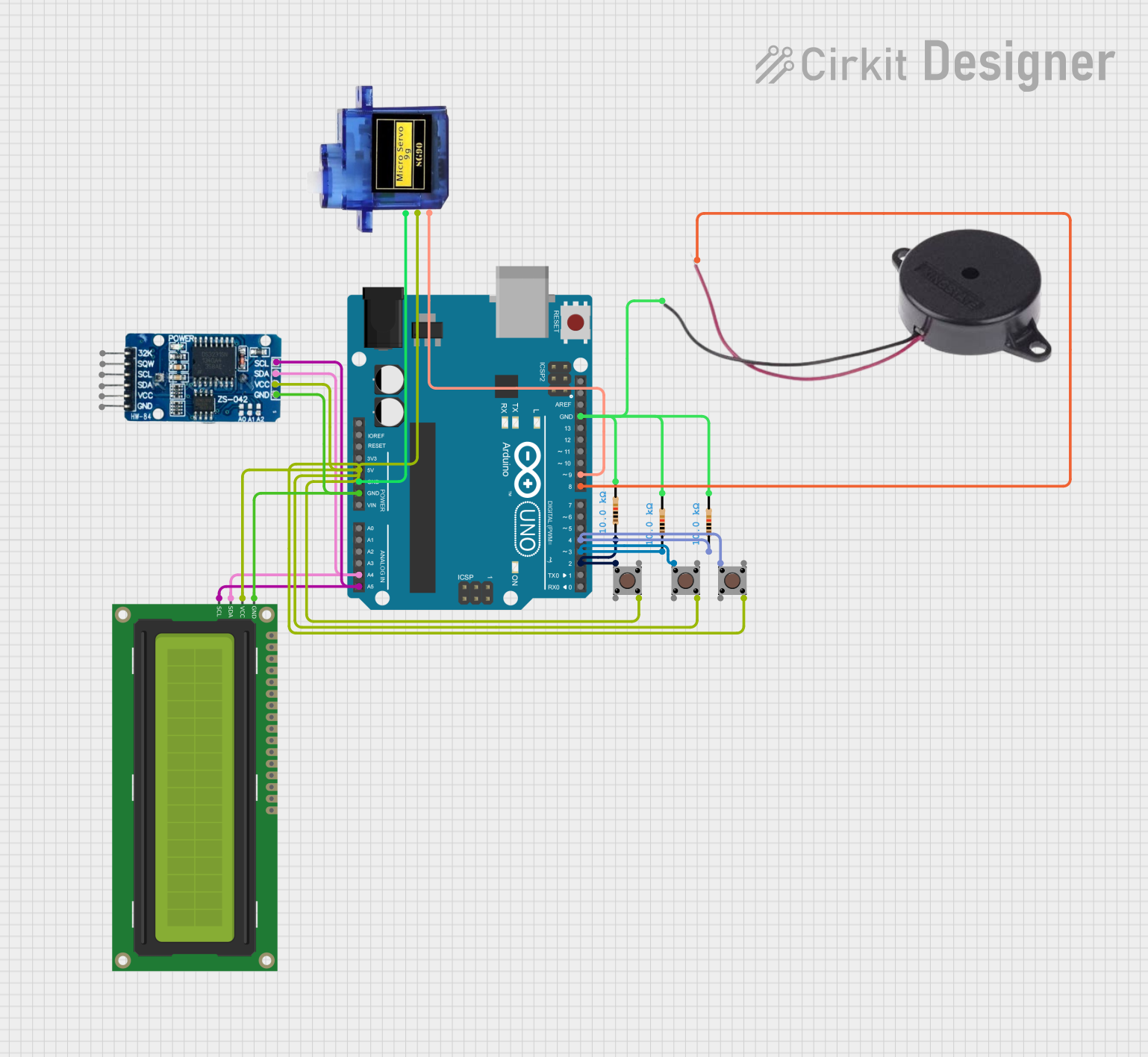
This circuit is designed to function as a medicine reminder and dispenser. It utilizes an Arduino UNO microcontroller to control a buzzer, a servo motor, an RTC (Real-Time Clock) module, an I2C LCD display, and multiple pushbuttons. The user can set up to three different timings for medicine reminders. At the set times, the buzzer will sound, and the servo motor will dispense the medicine.
Component List
Arduino UNO
- Description: Microcontroller board based on the ATmega328P.
- Pins: UNUSED, IOREF, Reset, 3.3V, 5V, GND, Vin, A0, A1, A2, A3, A4, A5, SCL, SDA, AREF, D13, D12, D11, D10, D9, D8, D7, D6, D5, D4, D3, D2, D1, D0
Buzzer
- Description: An electronic device that produces a sound when a voltage is applied.
- Pins: POSITIVE, NEGATIVE
Micro servo 9G
- Description: A small servo motor used for precise control of angular position.
- Pins: GND, +5V, PWM
RTC DS3231
- Description: Real-Time Clock module for keeping track of time.
- Pins: 32K, SQW, SCL, SDA, VCC, GND
Resistor (10k Ohms)
- Description: Resistor with a resistance of 10k Ohms.
- Pins: pin1, pin2
Pushbutton
- Description: A simple pushbutton switch.
- Pins: Pin 3 (out), Pin 4 (out), Pin 1 (in), Pin 2 (in)
16x2 I2C LCD
- Description: A 16x2 character LCD display with I2C interface.
- Pins: GND, VCC, SDA, SCL
Wiring Details
Arduino UNO
- 5V: Connected to VCC of RTC DS3231, VCC of 16x2 I2C LCD, +5V of Micro servo 9G, and Pin 4 (out) of all Pushbuttons.
- GND: Connected to GND of RTC DS3231, GND of 16x2 I2C LCD, GND of Micro servo 9G, pin2 of all Resistors, and NEGATIVE of Buzzer.
- A4: Connected to SDA of RTC DS3231 and SDA of 16x2 I2C LCD.
- A5: Connected to SCL of RTC DS3231 and SCL of 16x2 I2C LCD.
- D9: Connected to PWM of Micro servo 9G.
- D8: Connected to POSITIVE of Buzzer.
- D4: Connected to pin1 of Resistor and Pin 1 (in) of Pushbutton.
- D3: Connected to pin1 of Resistor and Pin 1 (in) of Pushbutton.
- D2: Connected to pin1 of Resistor and Pin 1 (in) of Pushbutton.
Buzzer
- POSITIVE: Connected to D8 of Arduino UNO.
- NEGATIVE: Connected to GND of Arduino UNO.
Micro servo 9G
- GND: Connected to GND of Arduino UNO.
- +5V: Connected to 5V of Arduino UNO.
- PWM: Connected to D9 of Arduino UNO.
RTC DS3231
- VCC: Connected to 5V of Arduino UNO.
- GND: Connected to GND of Arduino UNO.
- SDA: Connected to A4 of Arduino UNO.
- SCL: Connected to A5 of Arduino UNO.
Resistor (10k Ohms)
- pin1: Connected to D4, D3, and D2 of Arduino UNO.
- pin2: Connected to GND of Arduino UNO.
Pushbutton
- Pin 1 (in): Connected to pin1 of Resistor and D4, D3, and D2 of Arduino UNO.
- Pin 4 (out): Connected to 5V of Arduino UNO.
16x2 I2C LCD
- GND: Connected to GND of Arduino UNO.
- VCC: Connected to 5V of Arduino UNO.
- SDA: Connected to A4 of Arduino UNO.
- SCL: Connected to A5 of Arduino UNO.
Code Documentation
#include <Wire.h>
#include <RTClib.h>
#include <Servo.h>
#include <LiquidCrystal_I2C.h>

// Initialize components
RTC_DS3231 rtc;
Servo servo;
LiquidCrystal_I2C lcd(0x27, 16, 2);

// Pins for push buttons
const int buttonHourPin = 2;
const int buttonMinutePin = 3;
const int buttonConfirmPin = 4;

// Buzzer and Servo pins
const int buzzerPin = 8;
const int servoPin = 9;

// Timing variables
String timings[3] = {"00:00", "00:00", "00:00"};
int currentTimingIndex = 0;
int setHour = 0, setMinute = 0;
bool isSettingMode = true;

// Flag to prevent multiple triggers within the same minute
bool medicineDispensed = false;

void setup() {
  Serial.begin(9600);

  // Initialize LCD and components
  lcd.init();
  lcd.backlight();
  lcd.print("Hello, World!");
  servo.attach(servoPin);
  pinMode(buzzerPin, OUTPUT);

  // Initialize button pins
  pinMode(buttonHourPin, INPUT_PULLUP);
  pinMode(buttonMinutePin, INPUT_PULLUP);
  pinMode(buttonConfirmPin, INPUT_PULLUP);

  // Initialize RTC
  if (!rtc.begin()) {
    lcd.print("RTC not found!");
    while (1);
  }

  // Initial Servo Position
  servo.write(0);

  // Start setting mode
  lcd.clear();
  lcd.print("Set Timing 1");
}

void loop() {
  if (isSettingMode) {
    setTiming(); // Allow user to set timings
  } else {
    checkTimings(); // Monitor current time for alarms
  }
}

// Function to set timings
// Button state tracking
bool lastHourButtonState = HIGH;
bool lastMinuteButtonState = HIGH;
bool lastConfirmButtonState = HIGH;

void setTiming() {
  lcd.setCursor(0, 1);
  lcd.print("Time: ");
  lcd.print(formatTime(setHour, setMinute));

  // Read button states
  bool currentHourButtonState = digitalRead(buttonHourPin);
  bool currentMinuteButtonState = digitalRead(buttonMinutePin);
  bool currentConfirmButtonState = digitalRead(buttonConfirmPin);

  // Handle Hour Button
  if (lastHourButtonState == HIGH && currentHourButtonState == LOW) {
    setHour = (setHour + 1) % 24;
    delay(200); // Debounce delay
  }
  lastHourButtonState = currentHourButtonState;

  // Handle Minute Button
  if (lastMinuteButtonState == HIGH && currentMinuteButtonState == LOW) {
    setMinute = (setMinute + 1) % 60;
    delay(200); // Debounce delay
  }
  lastMinuteButtonState = currentMinuteButtonState;

  // Handle Confirm Button
  if (lastConfirmButtonState == HIGH && currentConfirmButtonState == LOW) {
    timings[currentTimingIndex] = formatTime(setHour, setMinute);
    currentTimingIndex++;

    if (currentTimingIndex < 3) {
      lcd.clear();
      lcd.print("Set Timing ");
      lcd.print(currentTimingIndex + 1);
      setHour = 0;
      setMinute = 0;
    } else {
      lcd.clear();
      lcd.print("Timings Set!");
      delay(2000);
      isSettingMode = false;
    }
    delay(200); // Debounce delay
  }
  lastConfirmButtonState = currentConfirmButtonState;
}

// Function to check timings and dispense medicine
void checkTimings() {
  DateTime now = rtc.now();
  String currentTime = formatTime(now.hour(), now.minute());

  for (String timing : timings) {
    if (currentTime == timing && !medicineDispensed) {
      alertUser();
      delay(5000); // Buzzer duration
      dispenseMedicine();
      medicineDispensed = true;
    }
  }

  // Reset flag after 1 minute
  if (millis() % 60000 == 0) {
    medicineDispensed = false;
  }

  delay(1000); // 1-second delay
}

// Function to alert the user
void alertUser() {
  lcd.clear();
  lcd.print("Take Medicine!");
  digitalWrite(buzzerPin, HIGH);
  delay(5000); // Buzzer on for 5 seconds
  digitalWrite(buzzerPin, LOW);
}

// Function to dispense medicine
void dispenseMedicine() {
  delay(30000); // Wait 30 seconds after alert
  servo.write(