Cirkit Designer
Your all-in-one circuit design IDE
Home /
Project Documentation
Arduino UNO Based Ultrasonic Distance Measurement with LED Indicator
Circuit Documentation
Summary of the Circuit
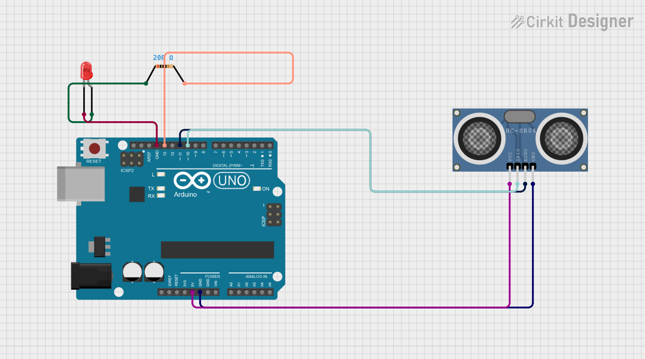
This circuit is designed around the Arduino UNO microcontroller board, which serves as the central processing unit. The circuit includes an HC-SR04 Ultrasonic Distance Sensor for measuring distances using ultrasonic waves, a red two-pin LED for visual indication, and a resistor to limit the current through the LED. The Arduino UNO is responsible for controlling the sensor and the LED based on the programmed logic.
Component List
Arduino UNO
- Description: A microcontroller board based on the ATmega328P.
- Pins: UNUSED, IOREF, Reset, 3.3V, 5V, GND, Vin, A0-A5, SCL, SDA, AREF, D0-D13.
- Purpose: Acts as the central processing unit for the circuit, controlling the sensor and LED.
LED: Two Pin (red)
- Description: A basic red LED with two pins: anode and cathode.
- Pins: cathode, anode.
- Purpose: Provides visual indication when powered.
HC-SR04 Ultrasonic Distance Sensor (Wokwi Compatible)
- Description: A sensor that measures distance by emitting ultrasonic waves and measuring the time it takes for the echo to return.
- Pins: VCC, TRIG, ECHO, GND.
- Purpose: Measures distances and provides feedback to the Arduino.
Resistor
- Description: A passive two-terminal electrical component that implements electrical resistance as a circuit element.
- Pins: pin1, pin2.
- Properties: Resistance value of 200 Ohms.
- Purpose: Limits the current flowing through the LED to prevent damage.
Wiring Details
Arduino UNO
- 5V pin connected to the VCC pin of the HC-SR04 Ultrasonic Distance Sensor.
- GND pin connected to:
- The GND pin of the HC-SR04 Ultrasonic Distance Sensor.
- The cathode of the LED.
- D13 pin connected to pin2 of the Resistor.
- D11 pin connected to the ECHO pin of the HC-SR04 Ultrasonic Distance Sensor.
- D10 pin connected to the TRIG pin of the HC-SR04 Ultrasonic Distance Sensor.
LED: Two Pin (red)
- Cathode connected to the GND pin of the Arduino UNO.
- Anode connected to pin1 of the Resistor.
HC-SR04 Ultrasonic Distance Sensor (Wokwi Compatible)
- VCC pin connected to the 5V pin of the Arduino UNO.
- GND pin connected to the GND pin of the Arduino UNO.
- ECHO pin connected to the D11 pin of the Arduino UNO.
- TRIG pin connected to the D10 pin of the Arduino UNO.
Resistor
- Pin1 connected to the anode of the LED.
- Pin2 connected to the D13 pin of the Arduino UNO.
Documented Code
Arduino UNO Code (sketch.ino)
void setup() {
  // put your setup code here, to run once:

}

void loop() {
  // put your main code here, to run repeatedly:

}
Additional Notes (documentation.txt)
No additional code documentation was provided.