Arduino Nano-Based Anti-Sleep Driver Alert System with RF Communication
Circuit Documentation
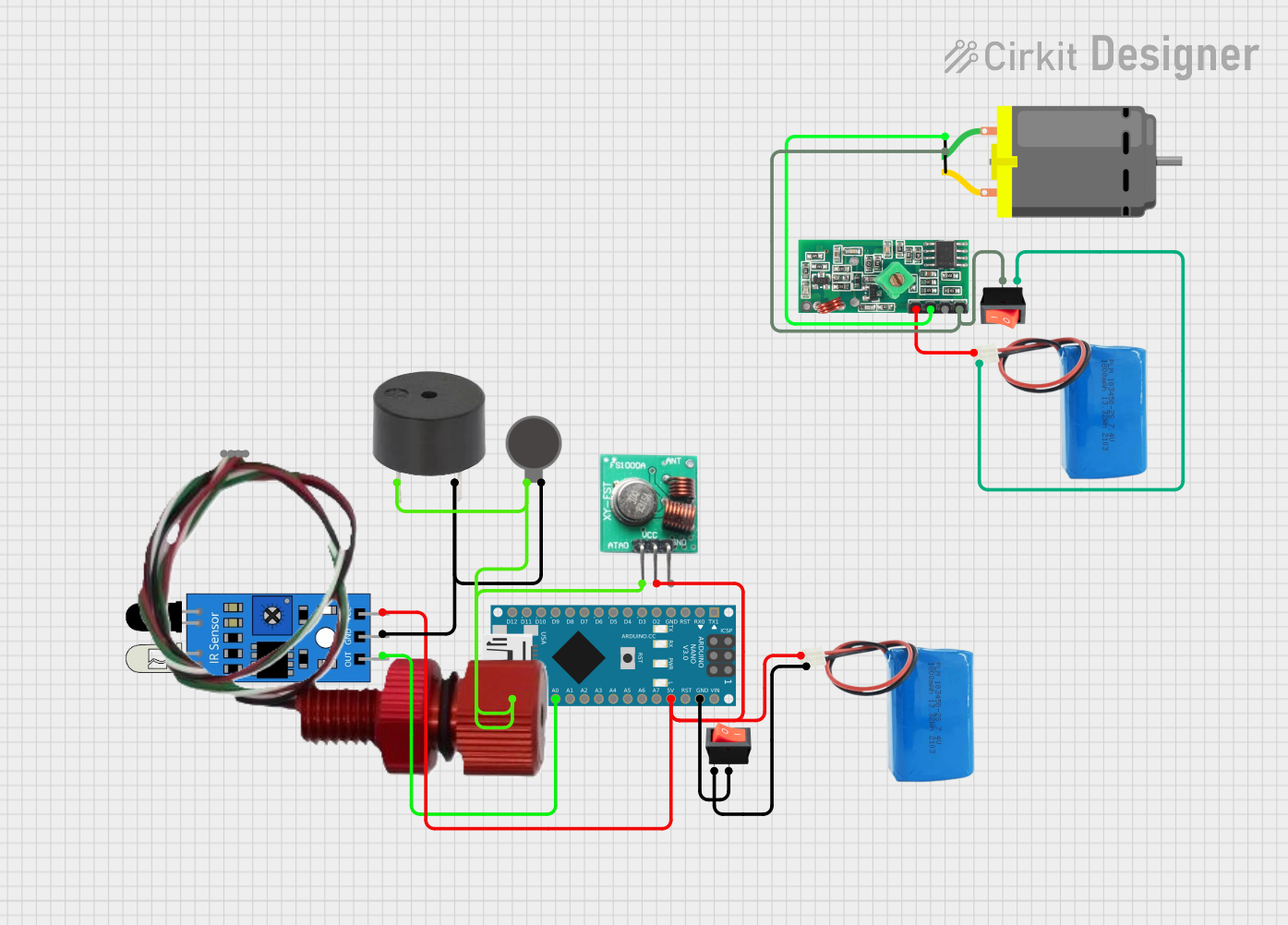
Summary of the Circuit
The circuit is designed for an anti-sleep system intended to prevent a driver from falling asleep at the wheel. It utilizes an Arduino Nano as the central microcontroller to process signals from an IR sensor that detects if the driver's eyes are closed. Upon detection, the system activates a buzzer and a vibration motor to alert the driver. Additionally, it sends a signal through a 433 MHz RF transmitter to communicate with the vehicle's system, potentially to slow down the car. The circuit is powered by two separate 5V batteries, each connected to different components through rocker switches.
Component List
Arduino Nano
- Microcontroller board based on the ATmega328P
- Features digital and analog I/O pins
- Can be powered via USB or an external power source
IR Sensor
- Detects proximity or the presence of an object
- Typically used for obstacle detection or motion sensing
Buzzer
- An electromechanical component that produces sound
- Used as an audible alert or alarm
Vibration Motor
- A small motor that generates vibration when powered
- Used to provide haptic feedback
Transmitter RF Module
- A wireless communication module operating at 433 MHz
- Used to send signals over short distances
5V Battery
- Provides power to the circuit
- Two instances are used to power different sections of the circuit
433 MHz RF Receiver Module
- Receives signals transmitted by the RF transmitter module
- Operates at the same frequency of 433 MHz
Rocker Switch
- A simple on/off switch
- Two instances are used to control power flow to different parts of the circuit
DC Motor
- Converts electrical energy into mechanical rotation
- Used for various actuation purposes in the circuit
Bar02 Pressure/Depth Sensor
- Measures pressure and can be used to determine depth underwater
- Utilizes I2C communication for interfacing with microcontrollers
Wiring Details
Arduino Nano
GNDconnected to the rocker switch (common ground)5Vconnected to the 5V battery (power supply)A0connected to the IR sensor (signal input)D13/SCKconnected to the buzzer, vibration motor, and RF transmitter module (signal output)
IR Sensor
vccconnected to the 5V battery (power supply)outconnected to Arduino Nano pinA0(signal output)gndconnected to common ground
Buzzer
PINconnected to Arduino Nano pinD13/SCK(signal input)GNDconnected to common ground
Vibration Motor
+connected to Arduino Nano pinD13/SCK(power supply)-connected to common ground
Transmitter RF Module
DATAconnected to Arduino Nano pinD13/SCK(signal input)VCCconnected to the 5V battery (power supply)GNDconnected to common ground
5V Battery
positiveconnected to various components for power supplynegativeconnected to common ground through rocker switches
433 MHz RF Receiver Module
VCCconnected to the 5V battery (power supply)DATAconnected to the DC motor (signal output)GNDconnected to common ground
Rocker Switch
outputconnected to common groundinputconnected to the negative terminal of the 5V batteries
DC Motor
pin 1connected to the 433 MHz RF receiver module (power supply)pin 2connected to common ground through a rocker switch
Bar02 Pressure/Depth Sensor
- Not connected in the provided net list
Documented Code
/*
 * Anti-Sleep Project
 * This Arduino Sketch reads the value from an IR sensor connected to pin A0.
 * If the sensor detects closed eyes, it activates a buzzer and a vibration
 * motor connected to pin D13. It also sends a signal via the 433 MHz RF
 * transmitter to slow down the car.
 */

#define SENSE A0
#define BUZZER_PIN 13
#define VIBRATOR_PIN 13
#define RF_TRANSMITTER_PIN 13

void setup() {
  pinMode(SENSE, INPUT);
  pinMode(BUZZER_PIN, OUTPUT);
  pinMode(VIBRATOR_PIN, OUTPUT);
  pinMode(RF_TRANSMITTER_PIN, OUTPUT);
}

void loop() {
  if (digitalRead(SENSE) == HIGH) {
    digitalWrite(BUZZER_PIN, HIGH);
    digitalWrite(VIBRATOR_PIN, HIGH);
    digitalWrite(RF_TRANSMITTER_PIN, HIGH);
  } else {
    digitalWrite(BUZZER_PIN, LOW);
    digitalWrite(VIBRATOR_PIN, LOW);
    digitalWrite(RF_TRANSMITTER_PIN, LOW);
  }
  delay(2000);
}
The code is written for the Arduino Nano and is responsible for reading the IR sensor's output, activating the buzzer and vibration motor, and sending a signal through the RF transmitter. The SENSE pin is set to read the IR sensor's output, and the BUZZER_PIN, VIBRATOR_PIN, and RF_TRANSMITTER_PIN are set to control the buzzer, vibration motor, and RF transmitter, respectively. The loop function checks the sensor's output and activates the alert systems accordingly.