
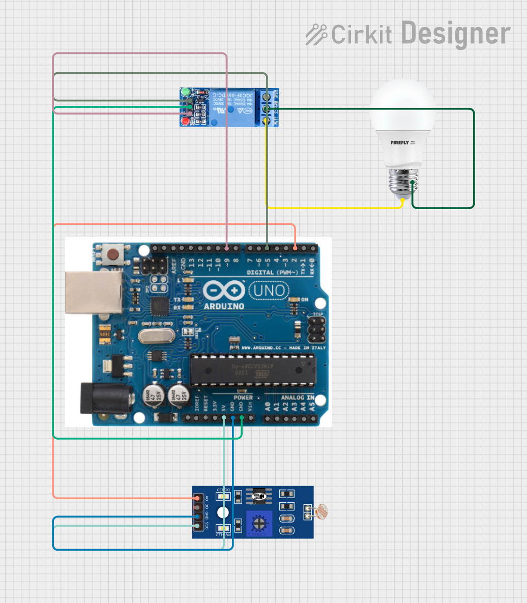
Circuit Documentation
Summary
This circuit is designed to control a light bulb based on the ambient light intensity detected by a Light Dependent Resistor (LDR). The system uses an Arduino UNO microcontroller to read the light intensity from the LDR and control a relay, which in turn switches the light bulb on or off.
Component List
Arduino UNO
- Description: A microcontroller board based on the ATmega328P.
- Pins: SDA, AREF, GND, 13, 12, 11, 10, 9, 8, 7, 6, 5, 4, 3, 2, 1, 0, A5, A4, A3, A2, A1, A0, Vin, 5V, 3.3V, RESET, IOREF, SCL
BULB
- Description: A standard light bulb.
- Pins: +, -
LDR
- Description: A Light Dependent Resistor used to measure light intensity.
- Pins: A0, D0, GND, VCC
1 Channel Relay 5V
- Description: A relay module used to switch the light bulb on or off.
- Pins: VCC, GND, IN, NC, COM, NO
Wiring Details
Arduino UNO
- Pin 5: Connected to VCC of the 1 Channel Relay 5V
- Pin GND: Connected to GND of the 1 Channel Relay 5V
- Pin 9: Connected to IN of the 1 Channel Relay 5V
- Pin 2: Connected to A0 of the LDR
- Pin GND: Connected to GND of the LDR
- Pin 5V: Connected to VCC of the LDR
BULB
- Pin +: Connected to NC of the 1 Channel Relay 5V
- Pin -: Connected to COM of the 1 Channel Relay 5V
LDR
- Pin A0: Connected to Pin 2 of the Arduino UNO
- Pin GND: Connected to GND of the Arduino UNO
- Pin VCC: Connected to 5V of the Arduino UNO
1 Channel Relay 5V
- Pin VCC: Connected to Pin 5 of the Arduino UNO
- Pin GND: Connected to GND of the Arduino UNO
- Pin IN: Connected to Pin 9 of the Arduino UNO
- Pin NC: Connected to Pin + of the BULB
- Pin COM: Connected to Pin - of the BULB
Code Documentation
#define LDR_PIN 2
#define Relay 9

const int LIGHT_THRESHOLD_HIGH = 800;    // High light intensity threshold
const int LIGHT_THRESHOLD_LOW = 500;     // Low light intensity threshold

void setup() {
  Serial.begin(115200);
  pinMode(LDR_PIN, INPUT); // DEFINE PIN AS INPUT SENSOR
  pinMode(Relay, OUTPUT);  // DEFINE PIN AS OUTPUT FOR RELAY
  Serial.println("LDR Sensor Test");
}

void loop() {
  int lightIntensity = analogRead(LDR_PIN); // Read sensor
  // Light intensity-based control
  if (lightIntensity >= LIGHT_THRESHOLD_HIGH) {
    digitalWrite(Relay, LOW); // Turn light OFF
    Serial.println("LIGHT IS OFF");
  } else if (lightIntensity <= LIGHT_THRESHOLD_LOW) {
    digitalWrite(Relay, HIGH); // Turn light ON
    Serial.println("LIGHT IS ON");
  } else {
    digitalWrite(Relay, LOW); // Turn light OFF
    Serial.println("LIGHT IS OFF");
  }

  // Debugging output
  Serial.print("Light Intensity: ");
  Serial.println(lightIntensity);

  delay(500); // Wait for 500 ms
}
This code reads the light intensity from the LDR and controls the relay to turn the light bulb on or off based on the predefined light intensity thresholds. The setup function initializes the serial communication and sets the pin modes. The loop function continuously reads the light intensity and controls the relay accordingly, providing debugging output via the serial monitor.