
Arduino UNO-Based Tilt and IR Sensor Controlled DC Motor System
View and Edit Project In Cirkit Designer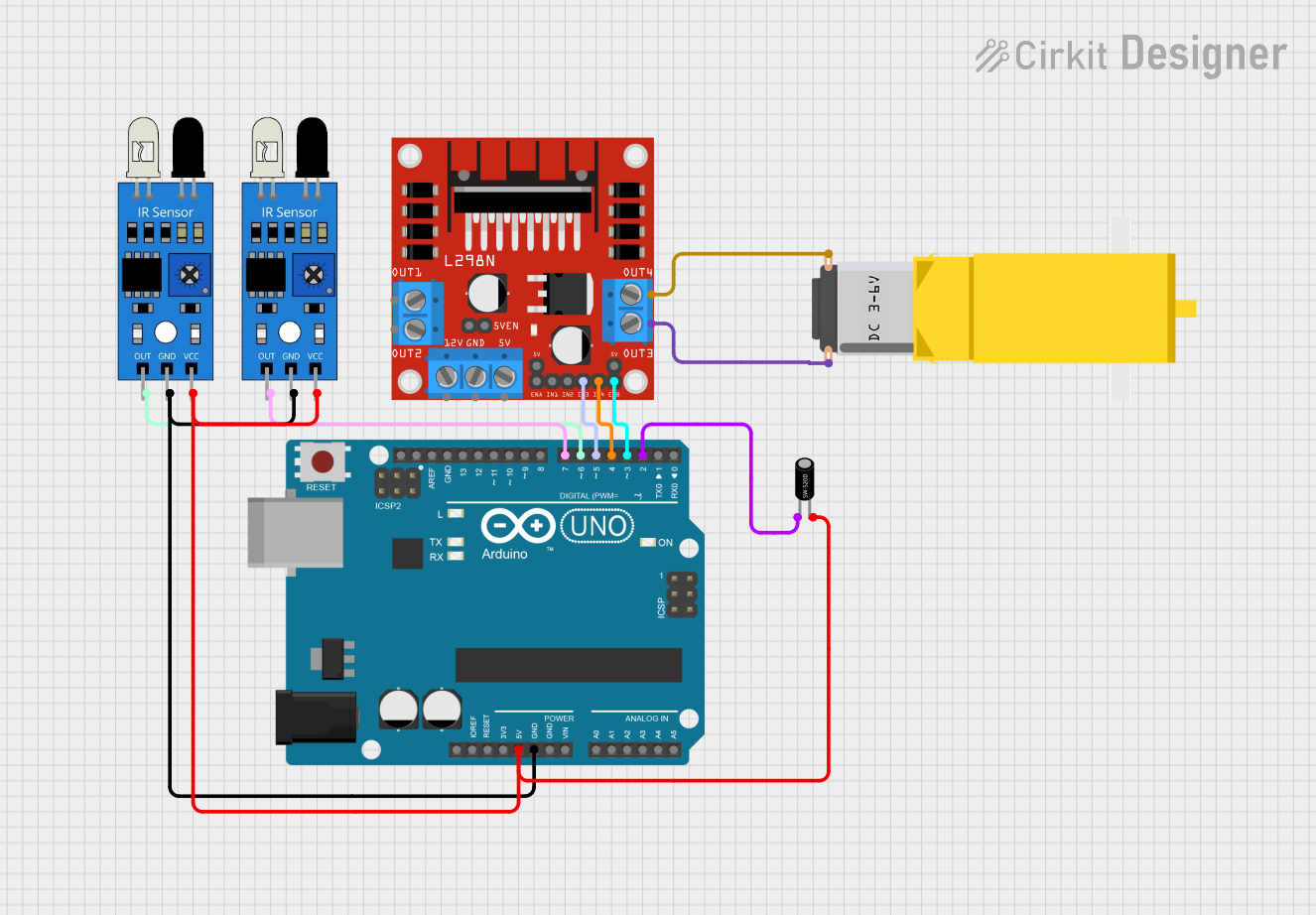
Circuit Documentation
Summary
This circuit involves an Arduino UNO microcontroller interfacing with various sensors and a motor driver to control a DC gear motor. The sensors include two IR sensors and a tilt sensor. The motor driver used is an L298N DC motor driver. The Arduino reads the sensor inputs and controls the motor based on the sensor states.
Component List
Arduino UNO
- Description: A microcontroller board based on the ATmega328P.
- Pins: UNUSED, IOREF, Reset, 3.3V, 5V, GND, Vin, A0, A1, A2, A3, A4, A5, SCL, SDA, AREF, D13, D12, D11, D10, D9, D8, D7, D6, D5, D4, D3, D2, D1, D0
L298N DC Motor Driver
- Description: A dual H-Bridge motor driver module that allows speed and direction control of two DC motors.
- Pins: OUT1, OUT2, 12V, GND, 5V, OUT3, OUT4, 5V-ENA-JMP-I, 5V-ENA-JMP-O, +5V-J1, +5V-J2, ENA, IN1, IN2, IN3, IN4, ENB
Gearmotor DC / Motorreductor
- Description: A DC gear motor used for driving mechanical systems.
- Pins: Pin1, Pin2
IR Sensor (x2)
- Description: An infrared sensor used for detecting objects or obstacles.
- Pins: out, gnd, vcc
Tilt Sensor
- Description: A sensor used to detect the tilt or orientation of an object.
- Pins: pin1, pin2
Wiring Details
Arduino UNO
- 5V: Connected to
vccof both IR sensors andpin2of the tilt sensor. - GND: Connected to
gndof both IR sensors. - D7: Connected to
outof the first IR sensor. - D6: Connected to
outof the second IR sensor. - D5: Connected to
IN3of the L298N DC motor driver. - D4: Connected to
IN4of the L298N DC motor driver. - D3: Connected to
ENBof the L298N DC motor driver. - D2: Connected to
pin1of the tilt sensor.
L298N DC Motor Driver
- OUT3: Connected to
Pin2of the Gearmotor DC. - OUT4: Connected to
Pin1of the Gearmotor DC. - IN3: Connected to
D5of the Arduino UNO. - IN4: Connected to
D4of the Arduino UNO. - ENB: Connected to
D3of the Arduino UNO.
Gearmotor DC / Motorreductor
- Pin1: Connected to
OUT4of the L298N DC motor driver. - Pin2: Connected to
OUT3of the L298N DC motor driver.
IR Sensor (1)
- vcc: Connected to
5Vof the Arduino UNO. - gnd: Connected to
GNDof the Arduino UNO. - out: Connected to
D7of the Arduino UNO.
IR Sensor (2)
- vcc: Connected to
5Vof the Arduino UNO. - gnd: Connected to
GNDof the Arduino UNO. - out: Connected to
D6of the Arduino UNO.
Tilt Sensor
- pin1: Connected to
D2of the Arduino UNO. - pin2: Connected to
5Vof the Arduino UNO.
Code Documentation
Arduino UNO Code
const int ir1 = 6;
const int ir2 = 7;
const int tilt = 2;
const int in1 = 3;
const int in2 = 4;
const int in3 = 5;

bool IsTilt = 0;
bool OnlyOneIR = 0;

void setup() {
  pinMode(ir1, INPUT);
  pinMode(ir2, INPUT);
  pinMode(tilt, INPUT);

  pinMode(in1, OUTPUT);
  pinMode(in2, OUTPUT);
  pinMode(in3, OUTPUT);

  Serial.begin(9600);
}

void loop() {
  int ir1State = digitalRead(ir1);
  int ir2State = digitalRead(ir2);
  int tiltState = digitalRead(tilt);

  IsTilt = (tiltState == 1);
  OnlyOneIR = (ir1State == 1 && ir2State == 1);

  Serial.print("IR1 State: ");
  Serial.print(ir1State);

  Serial.print("  IR2 State: ");
  Serial.print(ir2State);

  Serial.print("  Tilt State: ");
  Serial.print(tiltState);

  Serial.print("  IsTilt: ");
  Serial.print(IsTilt);

  Serial.print("  OnlyOneIR: ");
  Serial.println(OnlyOneIR);

  if (IsTilt && OnlyOneIR) {
    digitalWrite(in1, HIGH);
    digitalWrite(in2, LOW);
  } else {
    digitalWrite(in1, LOW);
    digitalWrite(in2, LOW);
  }

  delay(500);
}
IR Sensor Code
void setup() {
  // put your setup code here, to run once:
}

void loop() {
  // put your main code here, to run repeatedly:
}
This documentation provides a comprehensive overview of the circuit, including a summary, detailed component list, wiring details, and the code used in the microcontroller.