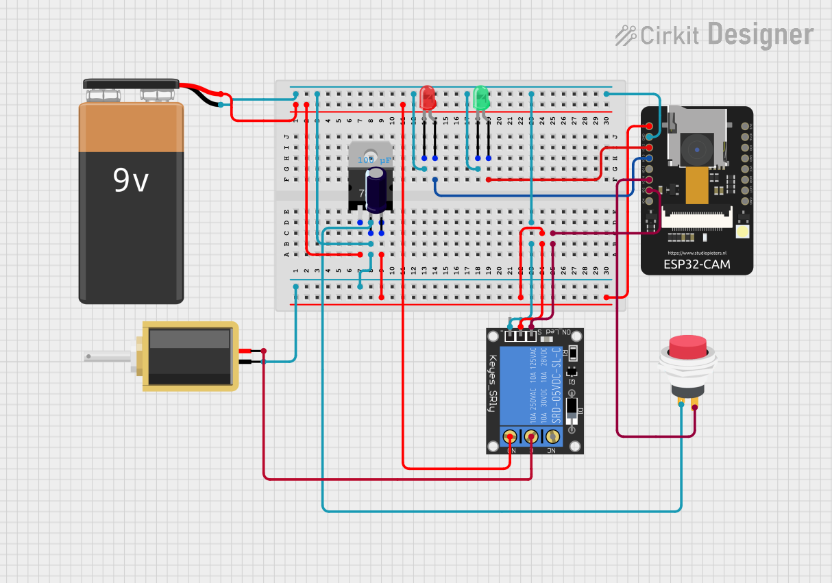
ESP32-CAM Based Smart Security System with Face Recognition

Smart Home Security System Circuit Documentation
Summary
The Smart Home Security System circuit is designed to integrate a camera module with motion detection and face recognition capabilities, along with various indicators and actuators to create a comprehensive security solution. The system uses an ESP32-CAM module to capture images and detect motion. When motion is detected, the system can trigger alerts, activate a solenoid lock, and control LED indicators. The circuit also includes a voltage regulator to ensure stable power supply to the ESP32-CAM, and a relay module to control the solenoid lock.
Component List
ESP32-CAM
- Description: A camera module with Wi-Fi capabilities that can be used for image capturing and processing.
- Pins: 5V, GND, IO12, IO13, IO15, IO14, IO2, IO4, VOT, VOR, VCC, IO0, IO16, 3V3
Solenoid
- Description: An electromechanical device used as a lock actuator.
- Pins: pin1, pin2
Voltage Regulator (V_REG_LD1117VXX)
- Description: A component that regulates input voltage to a stable output voltage.
- Pins: GND, OUT, IN
LED: Two Pin (green)
- Description: A green LED used as an indicator.
- Pins: cathode, anode
LED: Two Pin (red)
- Description: A red LED used as an indicator.
- Pins: cathode, anode
1-Channel Relay (5V 10A)
- Description: An electrically operated switch that can control the solenoid.
- Pins: NC, signal, C, power, NO, ground
9V Battery
- Description: A power source for the circuit.
- Pins: -, +
Electrolytic Capacitor
- Description: A capacitor used to filter out voltage spikes and smooth the power supply.
- Pins: -, +
- Properties: Capacitance: 0.0001 Farads
2Pin Push Switch
- Description: A switch used to trigger actions manually.
- Pins: Input +, Output +
Wiring Details
ESP32-CAM
- 5V connected to the V_REG_LD1117VXX OUT pin and 1-Channel Relay power pin.
- GND connected to the 9V Battery -, Solenoid pin1, V_REG_LD1117VXX GND pin, both LED cathodes, and 1-Channel Relay ground pin.
- IO12 connected to the green LED anode.
- IO13 connected to the red LED anode.
- IO2 connected to the 1-Channel Relay signal pin.
- IO14 connected to the 2Pin Push Switch Output + pin.
Solenoid
- pin1 connected to the 1-Channel Relay NO pin.
- pin2 connected to the 1-Channel Relay C pin.
V_REG_LD1117VXX
- IN connected to the 9V Battery + pin.
- OUT connected to the ESP32-CAM 5V pin.
- GND connected to the 9V Battery - pin.
LED: Two Pin (green)
- anode connected to the ESP32-CAM IO12 pin.
- cathode connected to the GND net.
LED: Two Pin (red)
- anode connected to the ESP32-CAM IO13 pin.
- cathode connected to the GND net.
1-Channel Relay (5V 10A)
- power connected to the V_REG_LD1117VXX OUT pin.
- signal connected to the ESP32-CAM IO2 pin.
- ground connected to the GND net.
- NO connected to the Solenoid pin1.
- C connected to the Solenoid pin2.
9V Battery
- connected to the V_REG_LD1117VXX IN pin.
- connected to the GND net.
Electrolytic Capacitor
- connected to the V_REG_LD1117VXX IN pin.
- connected to the GND net.
2Pin Push Switch
- Input + connected to the V_REG_LD1117VXX OUT pin.
- Output + connected to the ESP32-CAM IO14 pin.
Documented Code
The embedded code for the ESP32-CAM microcontroller is designed to handle camera initialization, Wi-Fi connectivity, and integration with the Blynk application for remote monitoring and control. The code includes functions for capturing photos, handling HTTP requests, and streaming video. It also contains the logic for face detection and recognition, which can trigger the solenoid lock and LED indicators based on the recognition result.
The code is organized into several files:
CameraFaceRecognitionDoorLock.ino: The main Arduino sketch file that sets up the camera, Wi-Fi, and Blynk application. It includes the logic for taking photos upon button press or external trigger and handling face recognition.camera_index.h: Contains the HTML web pages served by the ESP32-CAM when accessed through a web browser. It includes the camera's live stream and settings interface.camera_pins.h: Defines the pin assignments for different camera models, ensuring compatibility with the ESP32-CAM module used in this circuit.app_httpd.h: Sets up the web server on the ESP32-CAM and handles HTTP requests for image capture, streaming, and configuration changes.
The code leverages the esp_camera, WiFi, WiFiClient, BlynkSimpleEsp32, and other libraries to implement the features. It is structured to allow easy modification and updates to suit specific security system requirements.