
Circuit Documentation
Summary
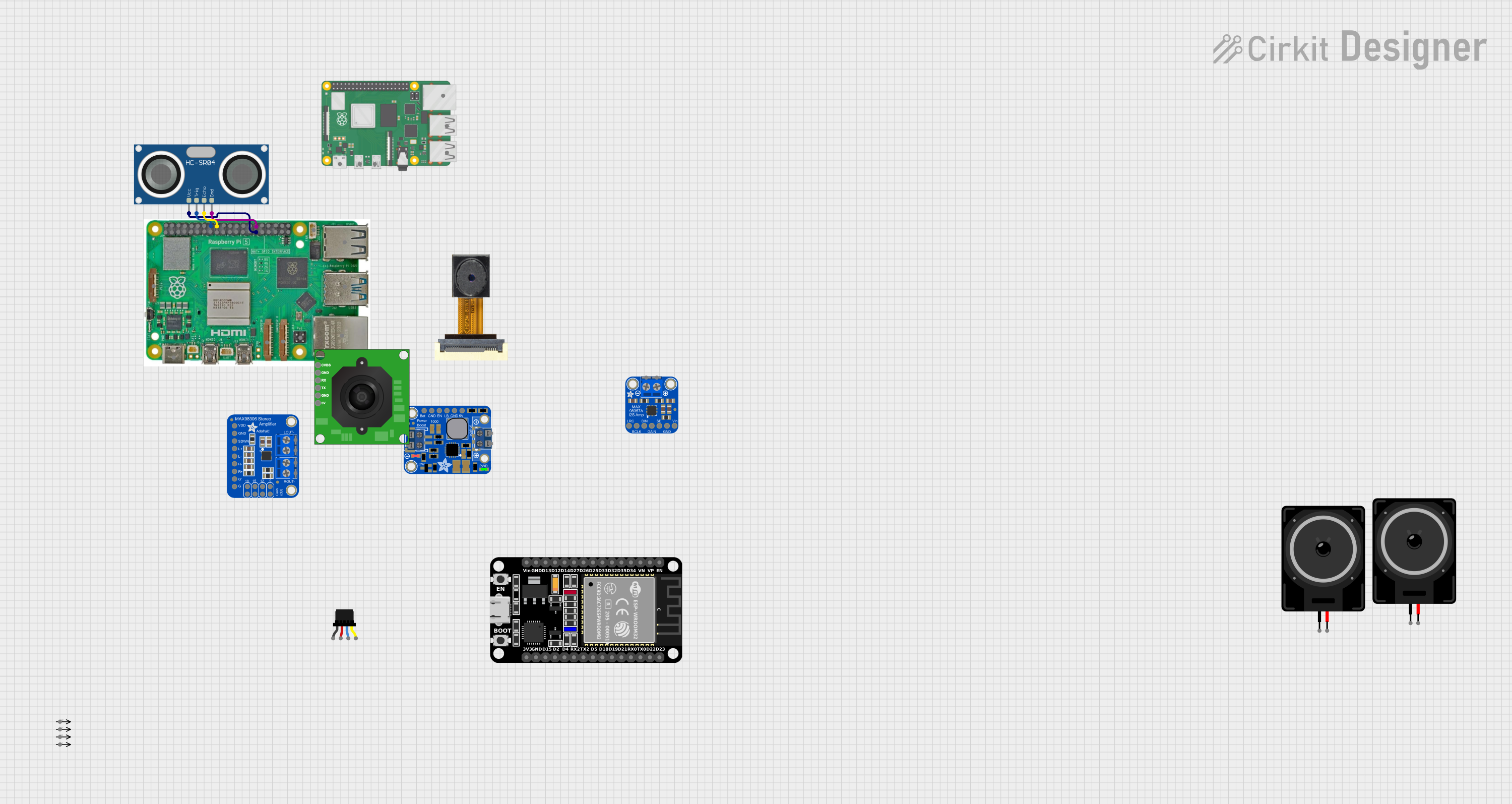
This document provides a detailed overview of a circuit that integrates various components including a Raspberry Pi 5, an HC-SR04 Ultrasonic Sensor, and other peripheral devices. The circuit is designed to interface these components for a specific application, with all electrical connections and wiring details provided.
Component List
ESP32 (30 pin)
- Description: A versatile microcontroller with Wi-Fi and Bluetooth capabilities.
- Pins: EN, VP, VN, D34, D35, D32, D33, D25, D26, D27, D14, D12, D13, GND, Vin, D23, D22, TX0, RX0, D21, D19, D18, D5, TX2, RX2, D4, D2, D15, 3V3
HC-SR04 Ultrasonic Sensor
- Description: A sensor used for measuring distance using ultrasonic waves.
- Pins: VCC, TRIG, ECHO, GND
OV2640 Camera Module
- Description: A camera module used for capturing images and video.
- Pins: 3.3V, GND, SIOC, SIOD, VSync, HRef, PCLK, XCLK, D9, D8, D7, D6, D5, D4, D3, D2, RET, PWDN
Loudspeaker
- Description: A device that converts electrical signals into sound.
- Pins: pin1, pin2
Adafruit MAX98357A
- Description: A digital-to-analog converter and amplifier for audio signals.
- Pins: VIN, GND, SD_MODE, GAIN, DIN, BCLK, LRCLK, VO+, VO-
Adafruit MAX98306 Stereo 3.7W Class D Audio Amplifier
- Description: A stereo audio amplifier for driving speakers.
- Pins: 9DB, GAIN1, VDD, 15DB, GND, GAIN2, IN_RIGHT+, IN_RIGHT-, IN_LEFT-, IN_LEFT+, SHUTDOWN, LOUT+, LOUT-, ROUT-, ROUT+
PowerBoost 1000 Basic Terminal
- Description: A power supply module for boosting voltage.
- Pins: VBAT, GND, ENABLE, LBO, 5.0V
Raspberry Pi 5
- Description: A single-board computer used for various applications.
- Pins: Type-C, Micro HDMI 1, Micro HDMI 2, Camera 1, Camera 2, PoE, Fan, PCIe, USB 3.0, USB 2.0, Ethernet, 5V, GND, 3.3v, GPIO 14, GPIO 15, GPIO 18, GPIO 23, GPIO 24, GPIO 25, GPIO 8, GPIO 7, GPIO 1, GPIO 12, GPIO 16, GPIO 20, GPIO 21, GPIO 2, GPIO 3, GPIO 4, GPIO 17, GPIO 27, GPIO 22, GPIO 10, GPIO 9, GPIO 11, GPIO 0, GPIO 5, GPIO 6, GPIO 13, GPIO 19, GPIO 26
Qwiic Cable - Breadboard Jumper (4-pin)
- Description: A cable for connecting Qwiic-enabled devices to a breadboard.
- Pins: GND, 3.3V, SDA, SCL
Raspberry Pi 4 B
- Description: A single-board computer used for various applications.
- Pins: usb 2.0, usb 3.0, Micro HDMI PORT 1, Micro HDMI PORT 2, usb-c Power Supply, Gigabit Ethernet
TTL Serial JPEG Camera
- Description: A camera module for capturing images and transmitting them over a serial interface.
- Pins: GND, RX, TX, CVBS, 5V
Wiring Details
Raspberry Pi 5
- GPIO 5 is connected to VCC of the HC-SR04 Ultrasonic Sensor.
- GPIO 23 is connected to TRIG of the HC-SR04 Ultrasonic Sensor.
- GPIO 24 is connected to ECHO of the HC-SR04 Ultrasonic Sensor.
- GND is connected to GND of the HC-SR04 Ultrasonic Sensor.
HC-SR04 Ultrasonic Sensor
- VCC is connected to GPIO 5 of the Raspberry Pi 5.
- TRIG is connected to GPIO 23 of the Raspberry Pi 5.
- ECHO is connected to GPIO 24 of the Raspberry Pi 5.
- GND is connected to GND of the Raspberry Pi 5.
ESP32 (30 pin)
- No specific connections provided in the net list.
OV2640 Camera Module
- No specific connections provided in the net list.
Loudspeaker
- No specific connections provided in the net list.
Adafruit MAX98357A
- No specific connections provided in the net list.
Adafruit MAX98306 Stereo 3.7W Class D Audio Amplifier
- No specific connections provided in the net list.
PowerBoost 1000 Basic Terminal
- No specific connections provided in the net list.
Qwiic Cable - Breadboard Jumper (4-pin)
- No specific connections provided in the net list.
Raspberry Pi 4 B
- No specific connections provided in the net list.
TTL Serial JPEG Camera
- No specific connections provided in the net list.
Code
No code was provided for this circuit.
This document provides a comprehensive overview of the components and their interconnections within the circuit. For further details or modifications, please refer to the specific datasheets and manuals of the individual components.