ESP32-Controlled Robot with Wi-Fi and Ultrasonic Sensors
Circuit Documentation
Summary
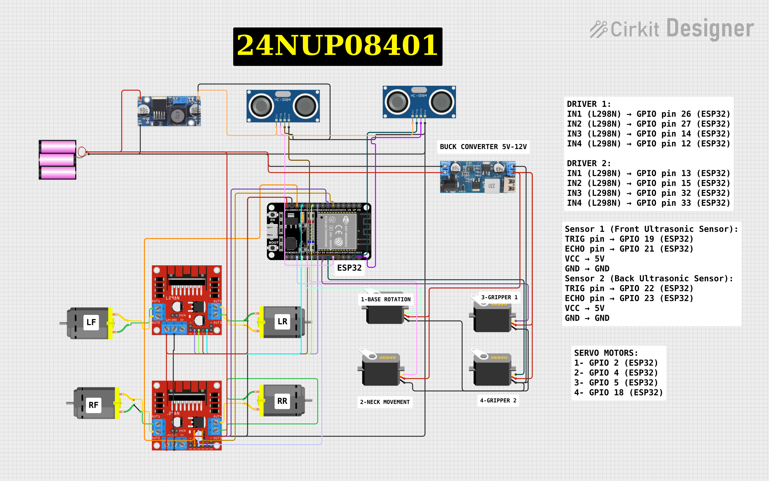
The circuit in question is designed to control multiple DC motors and servos using an ESP32 microcontroller. The ESP32 is programmed to interface with an L298N DC motor driver to control the direction and speed of the motors. Additionally, the ESP32 manages several servos by sending PWM signals. The circuit includes ultrasonic sensors for distance measurement and a power conversion system to step down voltage for the microcontroller and servos. The ESP32 also features Wi-Fi connectivity, allowing for remote control through a web server interface.
Component List
Microcontroller
- ESP32 (30 pin): A microcontroller with Wi-Fi capability that controls motors, servos, and reads sensor data.
Motor Drivers
- L298N DC Motor Driver: Used to control the direction and speed of DC motors.
Motors
- DC Motor: Four instances of DC motors controlled by the L298N motor drivers.
Servos
- Servo: Four instances of servos controlled by the ESP32 through PWM signals.
Sensors
- HC-SR04 Ultrasonic Sensor: Two instances of ultrasonic sensors used for distance measurement.
Power Conversion
- 12v to 5v Step Down Power Converter: Steps down voltage from 12V to 5V to power the servos.
- 48v to 5v Step Down Converter: Steps down voltage from 48V to 5V to power the ultrasonic sensors.
Power Supply
- Battery 12v: Provides power to the motor drivers and the step-down converter.
Comments
- Comment: Placeholder components that may represent annotations or notes in the circuit design.
Wiring Details
ESP32 (30 pin)
- D32, D33: Connected to L298N motor driver inputs for motor control.
- D26, D27, D14, D12, D13, D15: Connected to L298N motor driver inputs for motor control.
- D23, D22, D21, D19: Connected to HC-SR04 ultrasonic sensor trigger and echo pins.
- D18, D5, D4, D2: Connected to servo PWM control pins.
- Vin: Connected to 12V power supply.
- GND: Common ground with other components.
L298N DC Motor Driver (Two instances)
- IN1, IN2, IN3, IN4: Control inputs connected to ESP32 GPIOs.
- OUT1, OUT2, OUT3, OUT4: Outputs connected to DC motors.
- 12V: Power input connected to 12V battery.
- GND: Ground connection shared with the battery and ESP32.
DC Motor (Four instances)
- Pin 1, Pin 2: Connected to the corresponding outputs of the L298N motor drivers.
Servo (Four instances)
- Pulse: Connected to ESP32 GPIOs for PWM control.
- Vcc: Connected to 5V output from the step-down power converter.
- Gnd: Common ground with other components.
HC-SR04 Ultrasonic Sensor (Two instances)
- VCC: Connected to 5V output from the 48v to 5v step-down converter.
- TRIG, ECHO: Connected to ESP32 GPIOs for triggering and receiving echo.
- GND: Common ground with other components.
12v to 5v Step Down Power Converter
- VIN 9v-36v, VIN+: Connected to 12V battery.
- USB OUTPUT 5V, 5v OUTPUT: Provides 5V power to servos.
- GND: Common ground with other components.
Battery 12v
- +: Connected to 12V input of motor drivers and step-down converter.
- -: Common ground with other components.
48v to 5v Step Down Converter
- Out+, Out--: 5V output connected to ultrasonic sensors.
- In+, In--: 48V input (presumably from a higher voltage source).
Documented Code
#include <WiFi.h>
#include <ESPAsyncWebServer.h>
#include <Servo.h>

// Motor pins (L298N Motor Driver)
const int motor1Pin1 = 26;
const int motor1Pin2 = 27;
const int motor2Pin1 = 14;
const int motor2Pin2 = 12;
const int motor3Pin1 = 13;
const int motor3Pin2 = 15;
const int motor4Pin1 = 32;
const int motor4Pin2 = 33;

// Servo pins
Servo servo1;
Servo servo2;
Servo servo3;
Servo servo4;

const int servo1Pin = 2;
const int servo2Pin = 4;
const int servo3Pin = 5;
const int servo4Pin = 18;

// Wi-Fi credentials
const char *ssid = "YOUR_SSID";
const char *password = "YOUR_PASSWORD";

// Server object
AsyncWebServer server(80);

// Function to stop all motors
void stopMotors() {
  digitalWrite(motor1Pin1, LOW);
  digitalWrite(motor1Pin2, LOW);
  digitalWrite(motor2Pin1, LOW);
  digitalWrite(motor2Pin2, LOW);
  digitalWrite(motor3Pin1, LOW);
  digitalWrite(motor3Pin2, LOW);
  digitalWrite(motor4Pin1, LOW);
  digitalWrite(motor4Pin2, LOW);
}

void setup() {
  // Initialize Serial Monitor
  Serial.begin(115200);

  // Setup motor pins
  pinMode(motor1Pin1, OUTPUT);
  pinMode(motor1Pin2, OUTPUT);
  pinMode(motor2Pin1, OUTPUT);
  pinMode(motor2Pin2, OUTPUT);
  pinMode(motor3Pin1, OUTPUT);
  pinMode(motor3Pin2, OUTPUT);
  pinMode(motor4Pin1, OUTPUT);
  pinMode(motor4Pin2, OUTPUT);

  // Attach servos
  servo1.attach(servo1Pin);
  servo2.attach(servo2Pin);
  servo3.attach(servo3Pin);
  servo4.attach(servo4Pin);

  // Connect to Wi-Fi
  WiFi.begin(ssid, password);
  while (WiFi.status() != WL_CONNECTED) {
    delay(1000);
    Serial.println("Connecting to WiFi...");
  }
  Serial.println("Connected to WiFi");

  // Setup web server routes
  server.on("/", HTTP_GET, [](AsyncWebServerRequest *request) {
    request->send(200, "text/plain", "Control your RC Car");
  });

  // Control routes (adjust as per app logic)
  server.on("/forward", HTTP_GET, [](AsyncWebServerRequest *request) {
    digitalWrite(motor1Pin1, HIGH);
    digitalWrite(motor1Pin2, LOW);
    digitalWrite(motor2Pin1, HIGH);
    digitalWrite(motor2Pin2, LOW);
    digitalWrite(motor3Pin1, HIGH);
    digitalWrite(motor3Pin2, LOW);
    digitalWrite(motor4Pin1, HIGH);
    digitalWrite(motor4Pin2, LOW);
    request->send(200, "text/plain", "Moving Forward");
  });

  server.on("/stop", HTTP_GET, [](AsyncWebServerRequest *request) {
    stopMotors();
    request->send(200, "text/plain", "Stopped");
  });

  server.begin();
}

void loop() {
  // Handle other actions like servo movement in response to app commands
}
This code sets up the ESP32 microcontroller to control the motors and servos, connect to Wi-Fi, and serve a simple web interface for remote control. The stopMotors function is used to stop all motors, and the setup function initializes the system and sets up the web server routes. The loop function is left empty, as the ESPAsyncWebServer library handles HTTP requests asynchronously.