
Arduino Uno R3 Controlled Environmental Monitoring System with LCD Interface and Touch Sensor Interaction
View and Edit Project In Cirkit Designer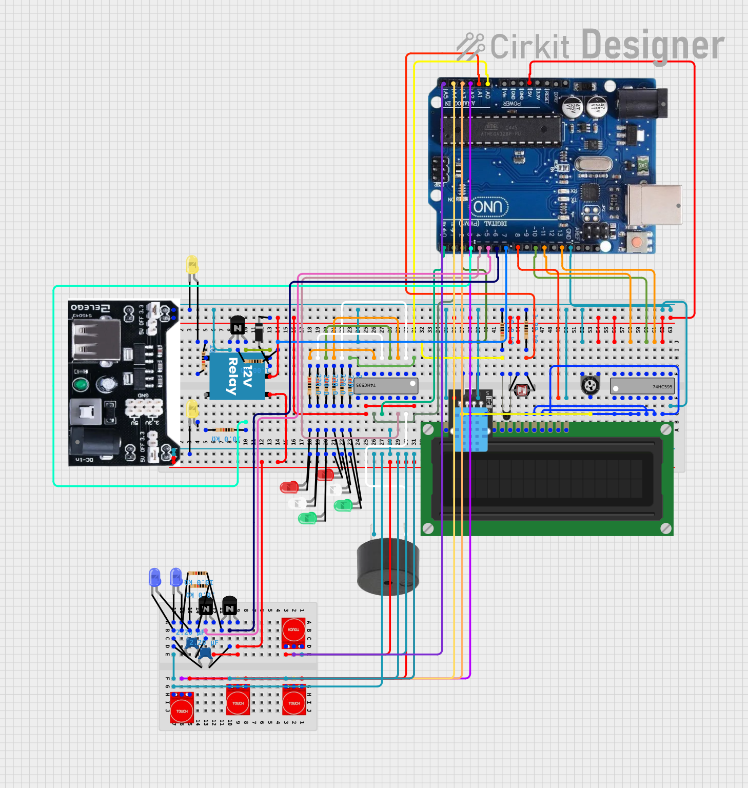
Circuit Documentation
Summary
This circuit is designed to interface with various sensors and actuators, including touch sensors, a DHT11 humidity and temperature sensor, LEDs, a buzzer, a relay, and an LCD display. It is controlled by an Arduino Uno R3 microcontroller, which manages input from the sensors and controls the output to the actuators based on the sensor readings and user input. The circuit includes components for user interaction, environmental monitoring, and feedback through visual and auditory means.
Component List
Microcontroller
- Arduino Uno R3: A microcontroller board based on the ATmega328P, with digital and analog I/O pins.
Sensors
- DHT11: A basic, ultra low-cost digital temperature and humidity sensor.
- Photocell (LDR): A light-dependent resistor whose resistance changes based on light intensity.
- NTC: A thermistor used for temperature sensing.
- Touch Sensor TTP233: A capacitive touch sensor module.
Actuators
- LCD Display (16 pin): A 16x2 character LCD display for user interface.
- LEDs: Red, green, white, blue, and yellow LEDs for visual feedback.
- Buzzer: An electronic buzzer for auditory feedback.
- 12V Relay: An electromechanical switch used for controlling high power devices.
Integrated Circuits
- 74HC595: An 8-bit shift register with output latches, providing additional digital outputs.
Discrete Components
- Resistors: Various resistors with different resistance values (220 Ohms, 1k Ohms, 10k Ohms).
- Ceramic Capacitors: Small-value capacitors for noise suppression and transient suppression.
- NPN Transistors (EBC): Bipolar junction transistors used as switches or amplifiers.
- Diode: A semiconductor device that allows current to flow in one direction only.
- Trimmer Potentiometer: A variable resistor used to adjust LCD contrast.
- Power mb V2: A power supply module.
Wiring Details
Arduino Uno R3
Connected to various sensors, actuators, and the 74HC595 shift register for controlling the circuit.
LCD Display (16 pin)
- VSS, R_W, K: Connected to GND.
- VDD: Connected to +5V.
- VO: Connected to the wiper of the trimmer potentiometer for contrast adjustment.
- RS, E, DB4-DB7: Controlled by the 74HC595 shift register.
- A: Connected to a digital pin for backlight control.
DHT11
- 5V: Connected to +5V.
- S: Connected to a digital pin for data reading.
- GND: Connected to GND.
Photocell (LDR)
Forms a voltage divider with a 1k Ohm resistor, connected to an analog input for light measurement.
NTC
Forms a voltage divider with a 10k Ohm resistor, connected to an analog input for temperature measurement.
Touch Sensor TTP233
- VCC: Connected to +5V.
- GND: Connected to GND.
- I/O: Connected to various analog pins for touch detection.
LEDs
Each LED is connected in series with a 220 Ohm resistor to limit current, with the cathode connected to GND and the anode controlled by the Arduino or the 74HC595 shift register.
Buzzer
Connected to a digital pin for sound generation.
12V Relay
- +: Connected to +12V through a diode for flyback protection.
- -: Connected to GND.
- C: Common terminal, used as the switch point.
- NC: Normally closed terminal, connected to a 10k Ohm resistor and an LED.
- NO: Normally open terminal, not detailed in the provided connections.
74HC595 Shift Register
- VCC: Connected to +5V.
- GND: Connected to GND.
- DS (DATA), ST_CP (RCLK), SH_CP (SRCLK), MR (SRCLR): Controlled by the Arduino for serial data input, storage register clock, shift register clock, and master reset, respectively.
- Q0-Q7: Control various LEDs and the LCD display.
NPN Transistors (EBC)
Used to switch higher current loads, such as the relay and LEDs, controlled by the Arduino through base resistors.
Power mb V2
Provides regulated power to the circuit components.
Documented Code
Arduino Uno R3 Code
//www.elegoo.com
//2016.12.9
#include <dht_nonblocking.h>
#include <ShiftedLCD.h>
#include <SPI.h>
#include <TimerOne.h>

// Sensors
int tempPin = 0;
int lightPin = 1;

// Display
LiquidCrystal lcd(10);
int backlightPin = 8;

// Humidity
#define DHT_SENSOR_TYPE DHT_TYPE_11
static const int DHT_SENSOR_PIN = 2;
DHT_nonblocking dht_sensor( DHT_SENSOR_PIN, DHT_SENSOR_TYPE );

// Controller
int latchPin = 0;
int clockPin = 1;
int dataPin = 4;
byte controls = 0;
bool loops = true;
bool justSwitched = true;

// Motors
int motor1Pin = 5;
int motor2Pin = 6;
int motorIncrease = 1;
int currentMotorSpeed = 0;

// BypassDamper
bool bypassActive = 0;
int damperPowerPin = 3;
int damperSwitchPin = 7;

// Buttons: analog port and debounce time
const int fanSpeed1Button = A2;
const int fanSpeed2Button = A3;
const int fanSpeed3Button = A4;
const int bypassButton = A5;
const int debounceDelay = 50; // milliseconds
bool buttonState = false;     // Current state of the button
bool lastButtonState = false; // Previous state of the button

// Light
bool lightState = false;
bool lastLightState = false;

/*
 * Poll for a measurement, keeping the state machine alive.  Returns
 * true if a measurement is available.
 */
static bool measure_environment( float *temperature, float *humidity )
{
  static unsigned long measurement_timestamp = millis( );

  /* Measure once every four seconds. */
  if( millis( ) - measurement_timestamp > 3000ul )
  {
    if( dht_sensor.measure( temperature, humidity ) == true )
    {
      measurement_timestamp = millis( );
      return( true );
    }
  }

  return( false );
}

void setup()
{
  pinMode(backlightPin, OUTPUT);
  digitalWrite(backlightPin, HIGH);

  lcd.begin(16, 2);

  pinMode(DHT_SENSOR_PIN, INPUT);
  pinMode(latchPin, OUTPUT);
  pinMode(dataPin, OUTPUT);
  pinMode(clockPin, OUTPUT);
  pinMode(motor1Pin, OUTPUT);
  pinMode(motor2Pin, OUTPUT);
  pinMode(fanSpeed1Button, INPUT);
  pinMode(fanSpeed2Button, INPUT);
  pinMode(fanSpeed3Button, INPUT);
  pinMode(bypassButton, INPUT);
  pinMode(damperSwitchPin, OUTPUT);

  pinMode(damperPowerPin, OUTPUT);

  Timer1.initialize(3 * 1000000);  // Set a timer interval of 1 second (1,000,000 microseconds)
  Timer1.attachInterrupt(toggleLoop);

  controls = 0;
  updateShiftRegister();
}
void loop()
{

  // Read data
  // Light
  int lightReading = analogRead(lightPin);


  // Buttons
  bool readingFS1B = analogRead(fanSpeed1Button) > 200; // Threshold for detecting press (adjust if necessary)
  bool readingFS2B = analogRead(fanSpeed2Button) > 200; // Threshold for detecting press (adjust if necessary)
  bool readingFS3B = analogRead(fanSpeed3Button) > 200; // Threshold for detecting press (adjust if necessary)
  bool readingBPB = analogRead(bypassButton) > 200; // Threshold for detecting press (adjust if necessary)

  bool readingFS = readingFS1B || readingFS2B || readingFS3B || readingBPB;

  // Debounce logic
  if (readingFS != lastButtonState) {
    delay(debounceDelay);
    if (readingFS != buttonState) {

      buttonState = readingFS;

      // If fan speed has changed, set new speed
      if (readingFS1B) {
        setMotorSpeed(1);
      } else if (readingFS2B) {
        setMotorSpeed(2);
      } else if (readingFS3B) {
        setMotorSpeed(3);
      }

      if (readingBPB) {
        bypassActive = !bypassActive;
      }

      // Toggle value on button release
      if (!buttonState) {

        // Fans Speed LEDs
        bitClear(controls,1);
        bitClear(controls,2);
        bitClear(controls,3);

        if (currentMotorSpeed != 0) {
          bitSet(controls,currentMotorSpeed);
        }
        // Bypass Damper
        bitClear(controls,5);

        if (bypassActive) {
          bitSet