
Circuit Documentation
Summary
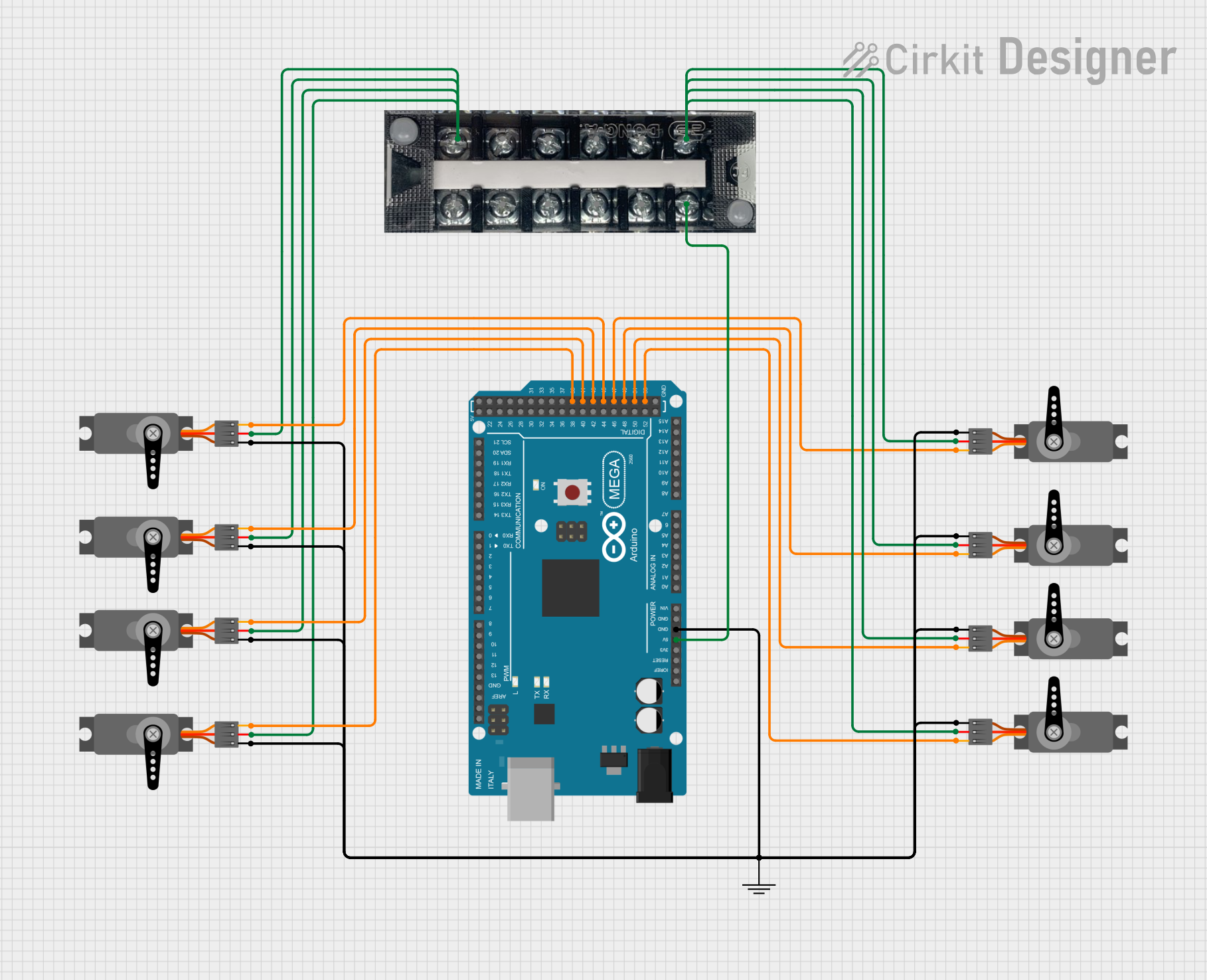
This circuit consists of multiple servo motors controlled by an Arduino Mega 2560 microcontroller. The servos are powered through a terminal block and are connected to the Arduino for PWM control. The circuit is designed to control the position of the servos based on the code running on the Arduino.
Component List
Servo Motor
- Description: A standard servo motor used for precise control of angular position.
- Pins: GND, VCC, PWM
Arduino Mega 2560
- Description: A microcontroller board based on the ATmega2560, used for controlling the servos.
- Pins: IOREF, RESET, 3V3, 5V, GND, VIN, A0-A15, D0-D53, AREF, SDA, SCL
Terminal Block KTB1 20A 6P
- Description: A terminal block used for distributing power to the servos.
- Pins: 1, 2, 3, 4, 5, 6
GND
- Description: A ground connection point.
Wiring Details
Servo Motor 1
- GND: Connected to GND (common ground net)
- VCC: Connected to Terminal Block KTB1 20A 6P pin 6
- PWM: Connected to Arduino Mega 2560 pin D43
Servo Motor 2
- GND: Connected to GND (common ground net)
- VCC: Connected to Terminal Block KTB1 20A 6P pin 1
- PWM: Connected to Arduino Mega 2560 pin D51
Servo Motor 3
- GND: Connected to GND (common ground net)
- VCC: Connected to Terminal Block KTB1 20A 6P pin 6
- PWM: Connected to Arduino Mega 2560 pin D39
Servo Motor 4
- GND: Connected to GND (common ground net)
- VCC: Connected to Terminal Block KTB1 20A 6P pin 1
- PWM: Connected to Arduino Mega 2560 pin D47
Servo Motor 5
- GND: Connected to GND (common ground net)
- VCC: Connected to Terminal Block KTB1 20A 6P pin 1
- PWM: Connected to Arduino Mega 2560 pin D49
Servo Motor 6
- GND: Connected to GND (common ground net)
- VCC: Connected to Terminal Block KTB1 20A 6P pin 6
- PWM: Connected to Arduino Mega 2560 pin D45
Servo Motor 7
- GND: Connected to GND (common ground net)
- VCC: Connected to Terminal Block KTB1 20A 6P pin 1
- PWM: Connected to Arduino Mega 2560 pin D41
Servo Motor 8
- GND: Connected to GND (common ground net)
- VCC: Connected to Terminal Block KTB1 20A 6P pin 1
- PWM: Connected to Arduino Mega 2560 pin D53
Arduino Mega 2560
- GND: Connected to GND (common ground net)
- 5V: Connected to Terminal Block KTB1 20A 6P pin 1
Terminal Block KTB1 20A 6P
- Pin 1: Connected to Arduino Mega 2560 pin 5V, Servo Motor 2 VCC, Servo Motor 4 VCC, Servo Motor 5 VCC, Servo Motor 7 VCC, Servo Motor 8 VCC
- Pin 6: Connected to Servo Motor 1 VCC, Servo Motor 3 VCC, Servo Motor 6 VCC
GND
- GND: Connected to all Servo Motor GND pins and Arduino Mega 2560 GND pin
Documented Code
Arduino Mega 2560 Code
void setup() {
  // put your setup code here, to run once:

}

void loop() {
  // put your main code here, to run repeatedly:

}
This code is a basic template for the Arduino Mega 2560. The setup function is used to initialize any settings, and the loop function contains the main code that runs repeatedly. You can add your servo control logic in these functions to control the servos as needed.