Arduino UNO Fire Detection System with SIM800L and Water Pump Control
Circuit Documentation
Summary
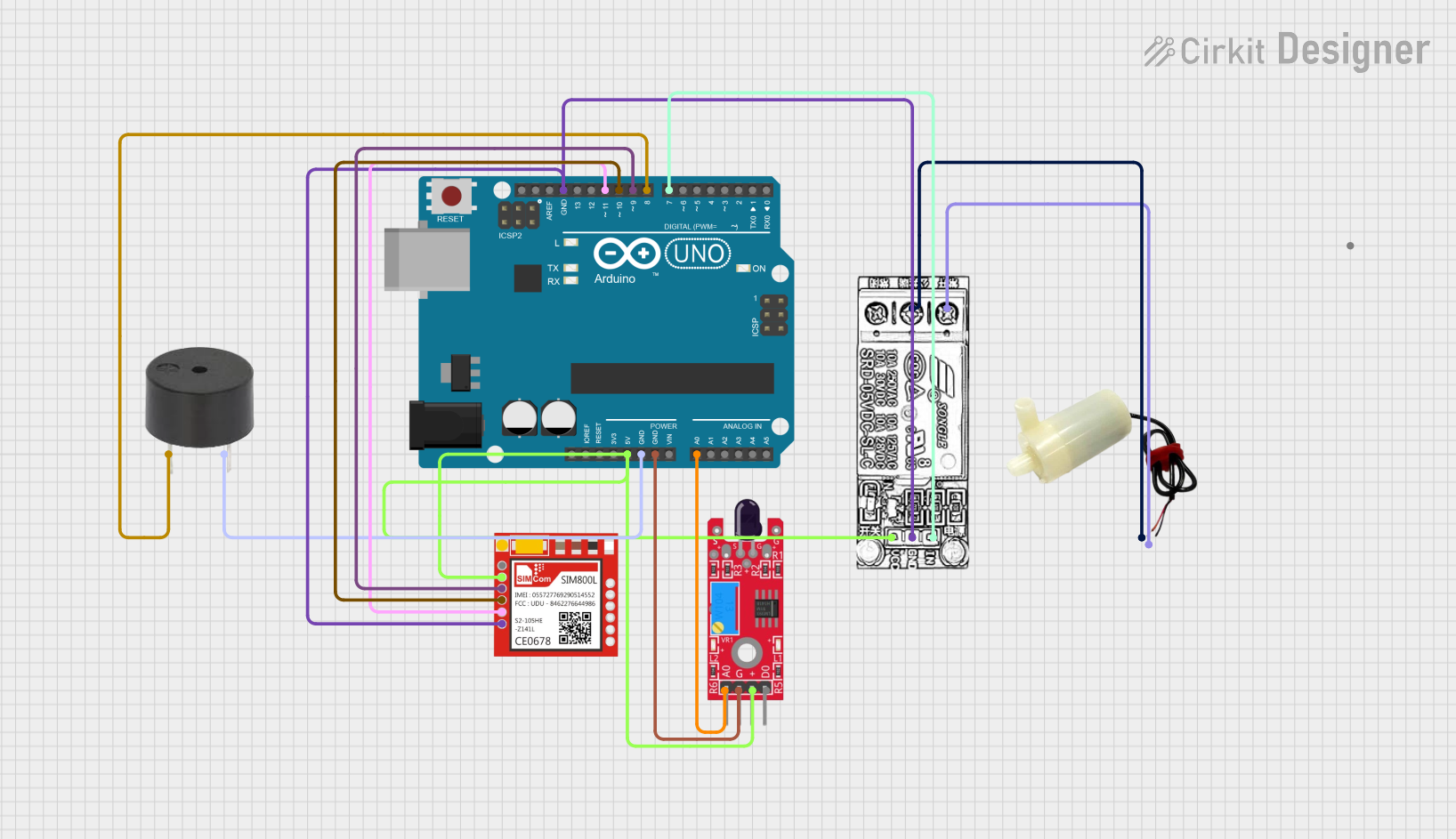
This circuit is designed to detect fire using a flame sensor and respond by activating a water pump and a buzzer. Additionally, it sends a warning message via a SIM800L GSM module. The core of the circuit is an Arduino UNO microcontroller, which interfaces with the flame sensor, buzzer, relay module, water pump, and SIM800L module.
Component List
Arduino UNO
- Description: A microcontroller board based on the ATmega328P.
- Pins: UNUSED, IOREF, Reset, 3.3V, 5V, GND, Vin, A0, A1, A2, A3, A4, A5, SCL, SDA, AREF, D13, D12, D11, D10, D9, D8, D7, D6, D5, D4, D3, D2, D1, D0
Sim800l
- Description: A GSM/GPRS module used for sending SMS messages.
- Pins: NET, RST, VCC, RXD, TXD, GND
Buzzer
- Description: An audio signaling device.
- Pins: PIN, GND
5V Mini Water Pump
- Description: A small water pump operating at 5V.
- Pins: positive pin, negative pin
KY-026 Flame Sensor
- Description: A sensor module used to detect fire or flame.
- Pins: AO, GND, VCC, DO
Relay Module
- Description: A module used to control high voltage devices with a low voltage signal.
- Pins: NC, COM, INPUT, GND, VCC
Wiring Details
Arduino UNO
- 5V: Connected to VCC of Relay Module, VCC of KY-026 Flame Sensor, and VCC of Sim800l.
- GND: Connected to GND of Buzzer, GND of KY-026 Flame Sensor, GND of Relay Module, and GND of Sim800l.
- A0: Connected to AO of KY-026 Flame Sensor.
- D11: Connected to TXD of Sim800l.
- D10: Connected to RXD of Sim800l.
- D9: Connected to RST of Sim800l.
- D8: Connected to PIN of Buzzer.
- D7: Connected to INPUT of Relay Module.
Sim800l
- VCC: Connected to 5V of Arduino UNO.
- GND: Connected to GND of Arduino UNO.
- TXD: Connected to D11 of Arduino UNO.
- RXD: Connected to D10 of Arduino UNO.
- RST: Connected to D9 of Arduino UNO.
Buzzer
- PIN: Connected to D8 of Arduino UNO.
- GND: Connected to GND of Arduino UNO.
5V Mini Water Pump
- positive pin: Connected to COM of Relay Module.
- negative pin: Connected to NC of Relay Module.
KY-026 Flame Sensor
- VCC: Connected to 5V of Arduino UNO.
- GND: Connected to GND of Arduino UNO.
- AO: Connected to A0 of Arduino UNO.
Relay Module
- VCC: Connected to 5V of Arduino UNO.
- GND: Connected to GND of Arduino UNO.
- INPUT: Connected to D7 of Arduino UNO.
- COM: Connected to positive pin of 5V Mini Water Pump.
- NC: Connected to negative pin of 5V Mini Water Pump.
Code Documentation
// Define pin connections
#define FLAME_SENSOR_PIN A0  // Flame sensor connected to Analog pin
#define BUZZER_PIN 8         // Buzzer connected to Digital pin
#define RELAY_PIN 7          // Relay connected to Digital pin
#define SIM800_TX 10         // SIM800L TX pin to Arduino RX
#define SIM800_RX 11         // SIM800L RX pin to Arduino TX
#define SIM800_PWR 9         // SIM800L power control pin

// Serial Communication for SIM800L
#include <SoftwareSerial.h>
SoftwareSerial sim800(SIM800_TX, SIM800_RX);  // RX, TX pins for SIM800L

void setup() {
  pinMode(FLAME_SENSOR_PIN, INPUT);
  pinMode(BUZZER_PIN, OUTPUT);
  pinMode(RELAY_PIN, OUTPUT);
  pinMode(SIM800_PWR, OUTPUT);

  // Initialize serial communications
  Serial.begin(9600);
  sim800.begin(9600); // Set the baud rate for SIM800L

  // Turn on the SIM800L module
  digitalWrite(SIM800_PWR, HIGH);
  delay(1000);  // Allow time for SIM800L to initialize

  Serial.println("System Initialized");
}

void loop() {
  int flameValue = analogRead(FLAME_SENSOR_PIN);  // Read flame sensor value

  if (flameValue > 500) {  // Fire detected (adjust this threshold if necessary)
    // Fire detected
    Serial.println("Fire detected!");

    // Activate buzzer
    digitalWrite(BUZZER_PIN, HIGH);

    // Activate relay (to control the pump)
    digitalWrite(RELAY_PIN, HIGH);

    // Send warning message
    sendWarningMessage();

    // Keep the buzzer and pump active for 10 seconds
    delay(10000);

    // Turn off the buzzer and pump
    digitalWrite(BUZZER_PIN, LOW);
    digitalWrite(RELAY_PIN, LOW);
  } else {
    // No fire detected, turn off the buzzer and pump
    digitalWrite(BUZZER_PIN, LOW);
    digitalWrite(RELAY_PIN, LOW);
  }

  delay(1000);  // Small delay to avoid excessive reads and spam
}

void sendWarningMessage() {
  sim800.println("AT");  // Test communication with the SIM800L module
  delay(1000);

  sim800.println("AT+CMGF=1");  // Set SMS mode to text
  delay(1000);

  sim800.println("AT+CMGS=\"+639935380795\"");  // Replace with your phone number
  delay(1000);

  sim800.println("Fire detected! Immediate action required.");
  delay(1000);

  sim800.write(26);  // Send SMS (Ctrl+Z to send message)
  delay(5000);  // Wait for the message to be sent

  Serial.println("Warning message sent.");
}
This code initializes the necessary pins and sets up serial communication with the SIM800L module. In the loop function, it continuously reads the flame sensor value. If a fire is detected (flame sensor value exceeds a threshold), it activates the buzzer and relay (which controls the water pump) and sends a warning message via the SIM800L module. The buzzer and pump remain active for 10 seconds before turning off. If no fire is detected, the buzzer and pump remain off.