
Arduino Pro Mini-Based Obstacle Avoidance Robot with Ultrasonic and IR Sensors
View and Edit Project In Cirkit Designer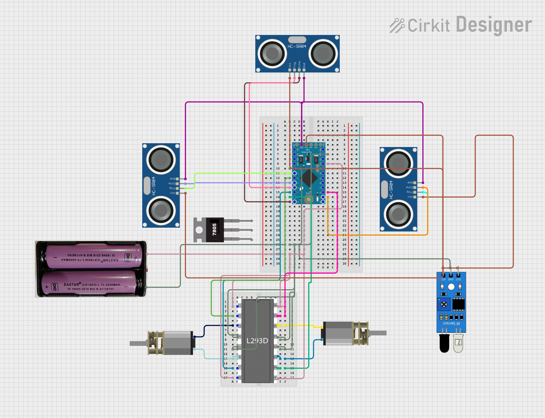
Circuit Documentation
Summary
This circuit is designed to interface multiple sensors and motors with an Arduino Pro Mini microcontroller. The circuit includes three HC-SR04 ultrasonic sensors, two DC Mini Metal Gear Motors, an IR sensor, and an L293D motor driver. The Arduino Pro Mini is programmed to read sensor data and control the motors based on the sensor inputs.
Component List
HC-SR04 Ultrasonic Sensor
- Pins: VCC, TRIG, ECHO, GND
- Description: Ultrasonic distance sensor used to measure distance to objects.
DC Mini Metal Gear Motor
- Pins: IN1, IN2
- Description: Small DC motor with metal gears for precise control.
7.4v Battery
- Pins: +, -
- Description: Power source for the circuit.
Arduino Pro Mini v13
- Pins: DTR, D0/TX, D1/RX, VCC, GND, A4, A5, RAW, RESET, A3, A2, A1, A0, D13/SCK, D12/MISO, D11 PWM/MOSI, D10 PWM/SS, D9 PWM, D8, D7, D6 PWM, D5 PWM, D4, D3 PWM, D2
- Description: Microcontroller used to control the circuit.
7805 Voltage Regulator
- Pins: Vin, Gnd, Vout
- Description: Voltage regulator to provide a stable 5V output.
IR Sensor
- Pins: out, gnd, vcc
- Description: Infrared sensor used to detect obstacles.
L293D Motor Driver
- Pins: enable 1, input 1, output 1, gnd, output 2, input 2, vs, vss, input 4, output 4, output 3, input 3, enable 2
- Description: Motor driver used to control the DC motors.
Wiring Details
HC-SR04 Ultrasonic Sensor 1
- VCC: Connected to VCC of Arduino Pro Mini
- TRIG: Connected to D3 PWM of Arduino Pro Mini
- ECHO: Connected to D5 PWM of Arduino Pro Mini
- GND: Connected to GND of Arduino Pro Mini
HC-SR04 Ultrasonic Sensor 2
- VCC: Connected to VCC of Arduino Pro Mini
- TRIG: Connected to D6 PWM of Arduino Pro Mini
- ECHO: Connected to D9 PWM of Arduino Pro Mini
- GND: Connected to GND of Arduino Pro Mini
HC-SR04 Ultrasonic Sensor 3
- VCC: Connected to VCC of Arduino Pro Mini
- TRIG: Connected to D10 PWM/SS of Arduino Pro Mini
- ECHO: Connected to D11 PWM/MOSI of Arduino Pro Mini
- GND: Connected to GND of Arduino Pro Mini
DC Mini Metal Gear Motor 1
- IN1: Connected to output 4 of L293D motor driver
- IN2: Connected to output 3 of L293D motor driver
DC Mini Metal Gear Motor 2
- IN1: Connected to output 2 of L293D motor driver
- IN2: Connected to output 1 of L293D motor driver
7.4v Battery
- +: Connected to VCC of Arduino Pro Mini and VS, enable 1, enable 2, VSS of L293D motor driver
- -: Connected to GND of Arduino Pro Mini and GND of L293D motor driver
Arduino Pro Mini v13
- D2: Connected to GND of IR sensor
- D3 PWM: Connected to TRIG of HC-SR04 Ultrasonic Sensor 1
- D4: Connected to input 1 of L293D motor driver
- D5 PWM: Connected to ECHO of HC-SR04 Ultrasonic Sensor 1
- D6 PWM: Connected to TRIG of HC-SR04 Ultrasonic Sensor 2
- D7: Connected to input 2 of L293D motor driver
- D8: Connected to input 3 of L293D motor driver
- D9 PWM: Connected to ECHO of HC-SR04 Ultrasonic Sensor 2
- D10 PWM/SS: Connected to TRIG of HC-SR04 Ultrasonic Sensor 3
- D11 PWM/MOSI: Connected to ECHO of HC-SR04 Ultrasonic Sensor 3
- D12/MISO: Connected to input 4 of L293D motor driver
- GND: Connected to GND of IR sensor, GND of L293D motor driver, and GND of HC-SR04 Ultrasonic Sensors
- VCC: Connected to VCC of IR sensor and VCC of HC-SR04 Ultrasonic Sensors
7805 Voltage Regulator
- Vin: Not connected in this circuit
- Gnd: Not connected in this circuit
- Vout: Not connected in this circuit
IR Sensor
- out: Not connected in this circuit
- gnd: Connected to GND of Arduino Pro Mini
- vcc: Connected to VCC of Arduino Pro Mini
L293D Motor Driver
- enable 1: Connected to VCC of Arduino Pro Mini
- input 1: Connected to D4 of Arduino Pro Mini
- output 1: Connected to IN2 of DC Mini Metal Gear Motor 2
- gnd: Connected to GND of Arduino Pro Mini
- output 2: Connected to IN1 of DC Mini Metal Gear Motor 2
- input 2: Connected to D7 of Arduino Pro Mini
- vs: Connected to VCC of Arduino Pro Mini
- vss: Connected to VCC of Arduino Pro Mini
- input 4: Connected to D12/MISO of Arduino Pro Mini
- output 4: Connected to IN1 of DC Mini Metal Gear Motor 1
- output 3: Connected to IN2 of DC Mini Metal Gear Motor 1
- input 3: Connected to D8 of Arduino Pro Mini
- enable 2: Connected to VCC of Arduino Pro Mini
Documented Code
// defining the pins
const int trigPin1 = 3;
const int echoPin1 = 5;
const int trigPin2 = 6;
const int echoPin2 = 9;
const int trigPin3 = 10;
const int echoPin3 = 11;
int irpin = 2;

// defining variables
long duration1;
long duration2;
long duration3;
int distanceleft;
int distancefront;
int distanceright;
int a = 0;

void setup() {
  pinMode(trigPin1, OUTPUT);
  pinMode(trigPin2, OUTPUT);
  pinMode(trigPin3, OUTPUT); // Sets the trigPin as an Output
  pinMode(echoPin1, INPUT);  // Sets the echoPin as an Input
  pinMode(echoPin2, INPUT);
  pinMode(echoPin3, INPUT);
  pinMode(irpin, INPUT);
  pinMode(4, OUTPUT);
  pinMode(7, OUTPUT);
  pinMode(8, OUTPUT);
  pinMode(12, OUTPUT);
}

void loop() {
  digitalWrite(trigPin1, LOW);
  delayMicroseconds(2);
  digitalWrite(trigPin1, HIGH);
  delayMicroseconds(10);
  digitalWrite(trigPin1, LOW);
  duration1 = pulseIn(echoPin1, HIGH);
  distanceleft = duration1 * 0.034 / 2;
  Serial.print("Distance1: ");
  Serial.println(distanceleft);

  digitalWrite(trigPin2, LOW);
  delayMicroseconds(2);
  digitalWrite(trigPin2, HIGH);
  delayMicroseconds(10);
  digitalWrite(trigPin2, LOW);
  duration2 = pulseIn(echoPin2, HIGH);
  distancefront = duration2 * 0.034 / 2;
  Serial.print("Distance2: ");
  Serial.println(distancefront);

  digitalWrite(trigPin3, LOW);
  delayMicroseconds(2);
  digitalWrite(trigPin3, HIGH);
  delayMicroseconds(10);
  digitalWrite(trigPin3, LOW);
  duration3 = pulseIn(echoPin3, HIGH);
  distanceright = duration3 * 0.034 / 2;
  Serial.print("Distance3: ");
  Serial.println(distanceright);

  int s = digitalRead(irpin);
  if (s == HIGH) {
    digitalWrite(4, LOW);
    digitalWrite(7, HIGH);
    digitalWrite(8, LOW);
    digitalWrite(12, HIGH);
    delay(1000);
    a = 1;
  }

  if ((a == 0) && (s == LOW) && (