Cirkit Designer
Your all-in-one circuit design IDE
Home /
Project Documentation
Arduino Mega 2560 Controlled Water Pump with LCD Interface and Bluetooth Connectivity
Circuit Documentation
Summary
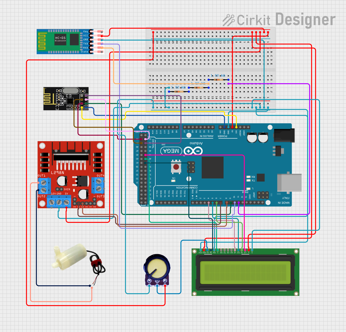
This document provides a detailed overview of a circuit that includes an Arduino Mega 2560 microcontroller as the central processing unit, interfaced with various peripherals including an LCD Display 16x2, NRF24L01 wireless module, L298N DC motor driver, a 5v mini water pump, HC-05 Bluetooth module, a potentiometer, and resistors. The circuit is designed to control a water pump and communicate wirelessly, with user inputs and system feedback provided via the LCD display and Bluetooth connection.
Component List
Arduino Mega 2560
- Microcontroller board based on the ATmega2560
- Provides numerous digital input/output pins, including PWM outputs, and analog inputs
- Features I2C, SPI, and UART communication capabilities
LCD Display 16x2
- Alphanumeric liquid crystal display capable of displaying 16 characters per line across 2 lines
- Utilizes a parallel interface for communication
NRF24L01
- A 2.4GHz wireless transceiver module
- Provides SPI communication interface
L298N DC Motor Driver
- Dual H-bridge motor driver capable of driving a pair of DC motors or a stepper motor
- Includes enable and input control pins for speed and direction control
5v Mini Water Pump
- A small DC water pump operating at 5 volts
- Used for pumping water in the system
HC-05 Bluetooth Module
- A widely used Bluetooth module for wireless communication
- Supports serial communication via UART
Potentiometer
- A three-terminal resistor with an adjustable voltage divider
- Used for adjusting LCD contrast or as an analog input
Resistors (1k Ohms)
- Passive components used to limit current or divide voltages
- Three resistors with a resistance of 1k Ohms each
Wiring Details
Arduino Mega 2560
D11 PWMconnected to a 1k Ohm resistorGNDconnected to common ground net5Vconnected to common 5V net3V3connected to NRF24L01 VCC (3V)D4 PWMtoDB4of LCD DisplayD5 PWMtoDB5of LCD DisplayD6 PWMtoDB6of LCD DisplayD7 PWMtoIN1of L298N Motor DriverD8 PWMtoIN2of L298N Motor DriverD9 PWMtoCEof NRF24L01D10 PWMtoTXDof HC-05D52toSCKof NRF24L01D50toMISOof NRF24L01D44toDB7of LCD DisplayD42toEof LCD DisplayD40toRSof LCD DisplayD53toCSNof NRF24L01D51toMOSIof NRF24L01
LCD Display 16x2
RW,VSS, andLEDKconnected to groundVDDandLEDAconnected to 5VDB4,DB5,DB6, andDB7connected to corresponding Arduino Mega 2560 pinsEandRSconnected to corresponding Arduino Mega 2560 pinsVOconnected to the wiper (output) of the potentiometer
NRF24L01
VCC (3V)connected to 3.3V from Arduino Mega 2560GNDconnected to common ground netCE,SCK,MISO,CSN, andMOSIconnected to corresponding Arduino Mega 2560 pins
L298N DC Motor Driver
GNDconnected to common ground net5Vconnected to common 5V netIN1andIN2connected to corresponding Arduino Mega 2560 pinsOUT1connected to the negative pin of the 5v mini water pumpOUT2connected to the positive pin of the 5v mini water pump
5v Mini Water Pump
Negative pinconnected toOUT1of L298N Motor DriverPositive pinconnected toOUT2of L298N Motor Driver
HC-05 Bluetooth Module
RXDconnected to a 1k Ohm resistor in series with another 1k Ohm resistor to groundGNDconnected to common ground netVCCconnected to common 5V netTXDconnected toD10 PWMof Arduino Mega 2560
Potentiometer
GNDconnected to common ground netVCCconnected to common 5V netOutputconnected toVOof LCD Display
Resistors (1k Ohms)
- One resistor connected between
D11 PWMof Arduino Mega 2560 and ground - Two resistors forming a voltage divider between
RXDof HC-05 and ground
Documented Code
Arduino Mega 2560 - sketch.ino
void setup() {
  // put your setup code here, to run once:

}

void loop() {
  // put your main code here, to run repeatedly:

}
Note: The provided code is a template and does not include any functional code. It needs to be populated with the logic to control the peripherals as per the circuit's requirements.