
STM32 and Arduino UNO Based Dual RS485 Communication Interface
View and Edit Project In Cirkit Designer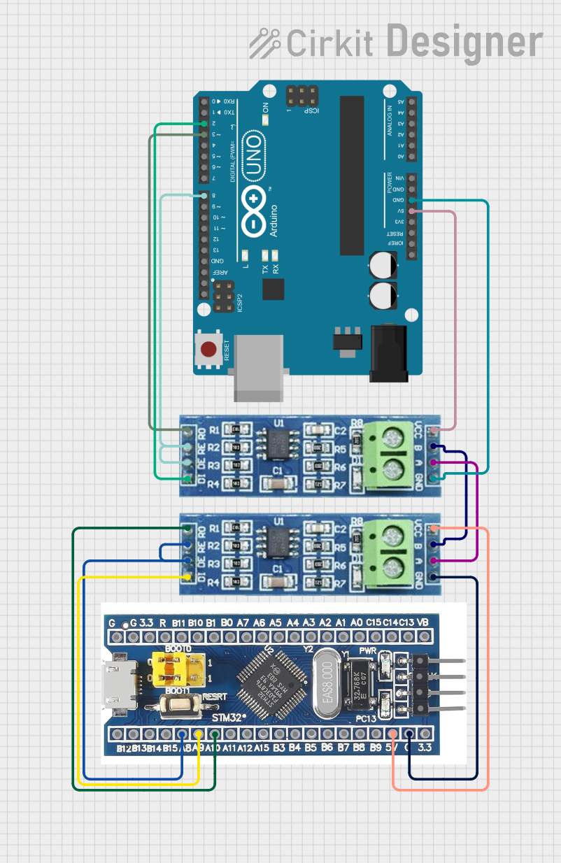
Circuit Documentation
Summary
The circuit in question is designed to interface an STM32F103C8T6 microcontroller with two RS485 transceiver modules and an Arduino UNO. The STM32F103C8T6 is responsible for handling the communication with one of the RS485 modules, while the Arduino UNO manages the other RS485 module. The RS485 modules are used for robust serial communication, typically in industrial environments. The circuit is powered by the 5V supply from the STM32F103C8T6 and the Arduino UNO.
Component List
STM32F103C8T6 Microcontroller
- Description: A 32-bit ARM Cortex-M3 microcontroller with a wide range of I/O capabilities and performance suitable for a variety of applications.
- Pins: GND, 3.3V, reset, B11, B10, B1, B0, A7, A6, A5, A4, A3, A2, A1, A0, C15, C14, C13, VBT, 3.3, 5V, B12, B13, B14, B15, A8, A9, A10, A11, A12, A15, B3, B4, B5, B6, B7, B8, B9, SWIO, SWCLK
Arduino UNO
- Description: A microcontroller board based on the ATmega328P, widely used for prototyping and educational purposes.
- Pins: UNUSED, IOREF, Reset, 3.3V, 5V, GND, Vin, A0, A1, A2, A3, A4, A5, SCL, SDA, AREF, D13, D12, D11, D10, D9, D8, D7, D6, D5, D4, D3, D2, D1, D0
RS485 Transceiver Module (2x)
- Description: A module for RS485 communication, which allows for long-distance and differential signal transmission.
- Pins: VCC, RO, RE, GND, B, A, DE, DI
Wiring Details
STM32F103C8T6 Microcontroller
- GND connected to RS485 GND
- 5V connected to RS485 VCC
- A8 connected to RS485 RE and DE (enabling and disabling the receiver and driver)
- A9 connected to RS485 DI (data input to the RS485 module)
- A10 connected to RS485 RO (data output from the RS485 module)
Arduino UNO
- 5V connected to RS485 VCC
- GND connected to RS485 GND
- D8 connected to RS485 RE and DE
- D3 connected to RS485 RO
- D2 connected to RS485 DI
RS485 Transceiver Modules
- Module 1:
- VCC connected to STM32F103C8T6 5V and Arduino UNO 5V
- GND connected to STM32F103C8T6 GND and Arduino UNO GND
- RE and DE connected to STM32F103C8T6 A8 and Arduino UNO D8
- DI connected to STM32F103C8T6 A9 and Arduino UNO D2
- RO connected to STM32F103C8T6 A10 and Arduino UNO D3
- B connected to B of the second RS485 module
- A connected to A of the second RS485 module
- Module 2:
- VCC connected to Arduino UNO 5V
- GND connected to Arduino UNO GND
- RE and DE connected to Arduino UNO D8
- DI connected to Arduino UNO D2
- RO connected to Arduino UNO D3
- B connected to B of the first RS485 module
- A connected to A of the first RS485 module
Documented Code
Arduino UNO Code (sketch.ino)
void setup() {
  // put your setup code here, to run once:

}

void loop() {
  // put your main code here, to run repeatedly:

}
Note: The provided code for the Arduino UNO is a template with empty setup and loop functions. The actual implementation should be added based on the specific requirements of the application.
Additional Files
- documentation.txt (Empty file, no code provided)
Note: The documentation.txt file is mentioned in the code list but does not contain any actual documentation or code.