
Arduino UNO-Based Fire Detection and Extinguishing Robot with Flame Sensors and L298N Motor Driver
View and Edit Project In Cirkit Designer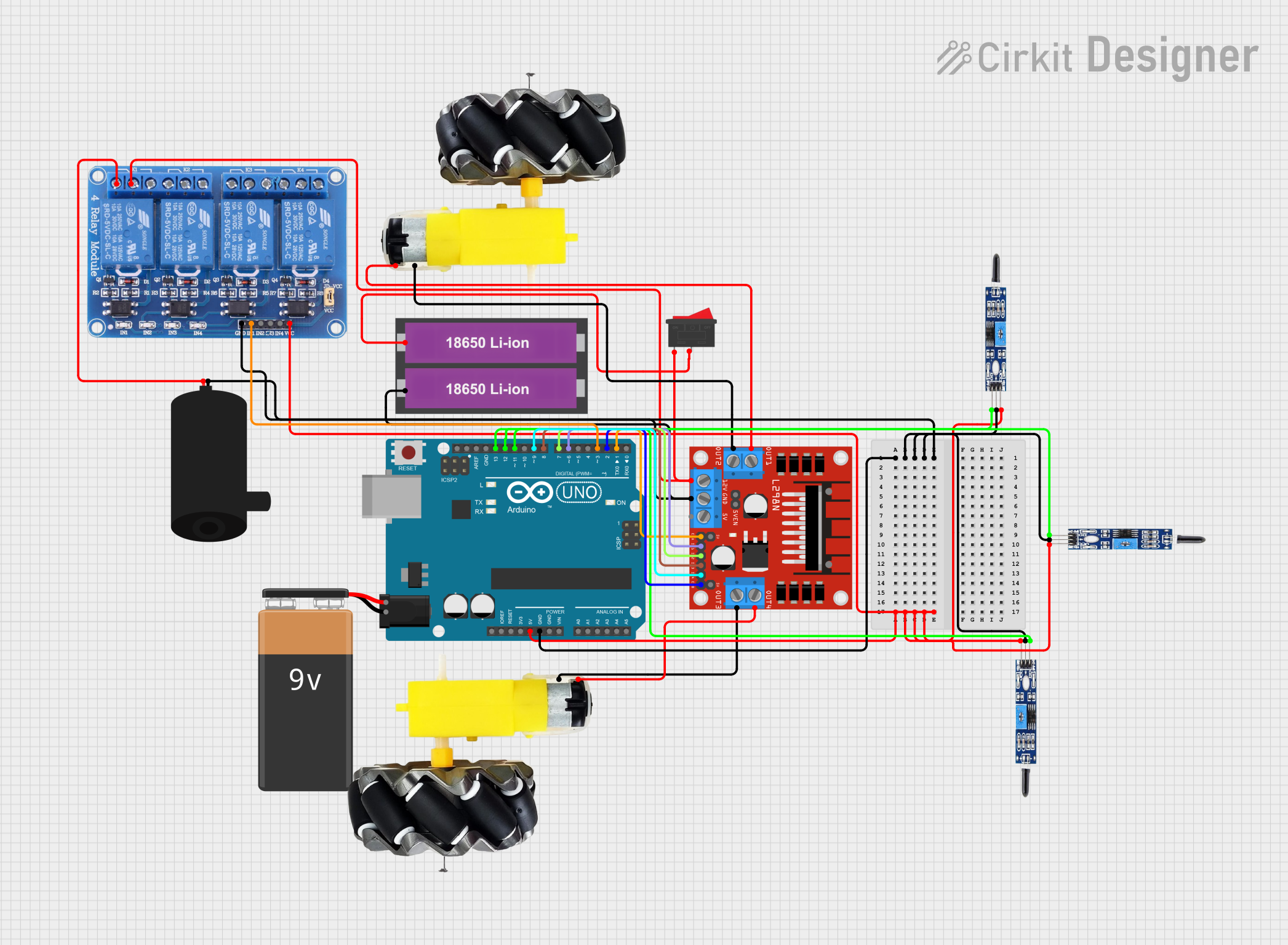
Circuit Documentation
Summary
This circuit is designed to interface an Arduino UNO with various sensors, a motor driver, a relay module, and other components to create a functional system. The Arduino UNO serves as the central microcontroller, receiving inputs from flame sensors and controlling motors, a water pump, and other peripherals through the motor driver and relay module.
Component List
Arduino UNO
- Description: A microcontroller board based on the ATmega328P.
- Pins: UNUSED, IOREF, Reset, 3.3V, 5V, GND, Vin, A0, A1, A2, A3, A4, A5, SCL, SDA, AREF, D13, D12, D11, D10, D9, D8, D7, D6, D5, D4, D3, D2, D1, D0
9V Battery
- Description: A standard 9V battery.
- Pins: -, +
L298N DC Motor Driver
- Description: A dual H-Bridge motor driver.
- Pins: OUT1, OUT2, 12V, GND, 5V, OUT3, OUT4, 5V-ENA-JMP-I, 5V-ENA-JMP-O, +5V-J1, +5V-J2, ENA, IN1, IN2, IN3, IN4, ENB
Motor and Wheels
- Description: A motor with attached wheels.
- Pins: vcc, GND
Flame Sensor
- Description: A sensor to detect flame.
- Pins: VCC, GND, OUTPUT
18650 Li-ion Battery x 2
- Description: Two 18650 Li-ion batteries.
- Pins: +, -
Rocker Switch
- Description: A simple on/off switch.
- Pins: 1, 2
Relay 4 Channel 5V
- Description: A 4-channel relay module.
- Pins: GND, IN1, IN2, IN3, IN4, VCC, COM1, COM2, COM3, COM4, NO1, NO2, NO3, NO4, NC1, NC2, NC3, NC4
Water Pump
- Description: A small water pump.
- Pins: positive, negative
Wiring Details
Arduino UNO
GND connected to:
- Flame Sensor (GND)
- Flame Sensor (GND)
- Flame Sensor (GND)
- Relay 4 Channel 5V (GND)
5V connected to:
- Flame Sensor (VCC)
- Flame Sensor (VCC)
- Flame Sensor (VCC)
- Relay 4 Channel 5V (VCC)
D13 connected to:
- Flame Sensor (OUTPUT)
D12 connected to:
- Flame Sensor (OUTPUT)
D11 connected to:
- Flame Sensor (OUTPUT)
D9 connected to:
- L298N DC Motor Driver (IN4)
D8 connected to:
- L298N DC Motor Driver (IN3)
D7 connected to:
- L298N DC Motor Driver (IN2)
D6 connected to:
- L298N DC Motor Driver (IN1)
D3 connected to:
- Relay 4 Channel 5V (IN1)
D2 connected to:
- L298N DC Motor Driver (ENB)
D1 connected to:
- L298N DC Motor Driver (ENA)
9V Battery
- + not connected
- - not connected
L298N DC Motor Driver
GND connected to:
- Water Pump (negative)
- 18650 Li-ion Battery x 2 (-)
12V connected to:
- Rocker Switch (1)
OUT1 connected to:
- Motor and Wheels (vcc)
OUT2 connected to:
- Motor and Wheels (GND)
OUT3 connected to:
- Motor and Wheels (GND)
OUT4 connected to:
- Motor and Wheels (vcc)
Motor and Wheels
vcc connected to:
- L298N DC Motor Driver (OUT1)
- L298N DC Motor Driver (OUT4)
GND connected to:
- L298N DC Motor Driver (OUT2)
- L298N DC Motor Driver (OUT3)
Flame Sensor
GND connected to:
- Arduino UNO (GND)
- Arduino UNO (GND)
- Arduino UNO (GND)
VCC connected to:
- Arduino UNO (5V)
- Arduino UNO (5V)
- Arduino UNO (5V)
OUTPUT connected to:
- Arduino UNO (D13)
- Arduino UNO (D12)
- Arduino UNO (D11)
18650 Li-ion Battery x 2
+ connected to:
- Rocker Switch (2)
- connected to:
- L298N DC Motor Driver (GND)
Rocker Switch
1 connected to:
- L298N DC Motor Driver (12V)
- Relay 4 Channel 5V (COM1)
2 connected to:
- 18650 Li-ion Battery x 2 (+)
Relay 4 Channel 5V
GND connected to:
- Arduino UNO (GND)
VCC connected to:
- Arduino UNO (5V)
IN1 connected to:
- Arduino UNO (D3)
COM1 connected to:
- Rocker Switch (1)
NC1 connected to:
- Water Pump (positive)
Water Pump
positive connected to:
- Relay 4 Channel 5V (NC1)
negative connected to:
- L298N DC Motor Driver (GND)
Documented Code
Arduino UNO Code (sketch.ino)
void setup() {
  // put your setup code here, to run once:

}

void loop() {
  // put your main code here, to run repeatedly:

}
Additional Documentation (documentation.txt)
This documentation provides a comprehensive overview of the circuit, including a summary, detailed component list, wiring details, and the code used in the Arduino UNO.