Arduino UNO and L298N Motor Driver-Based Obstacle Avoidance Robot with Ultrasonic Sensors
Circuit Documentation
Summary
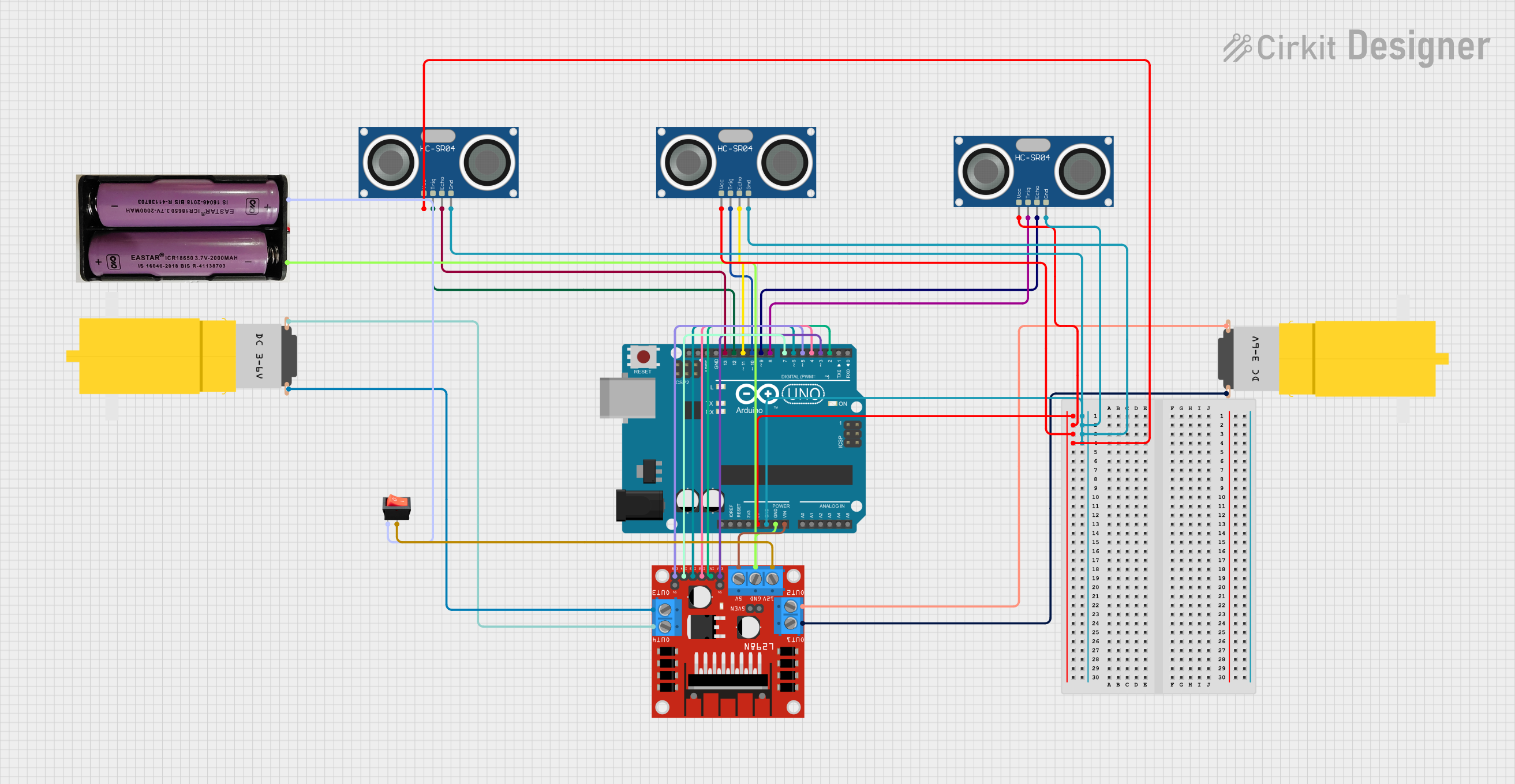
This circuit involves an Arduino UNO microcontroller interfacing with multiple HC-SR04 ultrasonic sensors, an L298N DC motor driver, and two hobby motors. The circuit is powered by a 7.4V battery and includes a rocker switch for power control. The Arduino UNO is programmed to control the motor driver and read data from the ultrasonic sensors.
Component List
Arduino UNO
- Description: A microcontroller board based on the ATmega328P.
- Pins: UNUSED, IOREF, Reset, 3.3V, 5V, GND, Vin, A0, A1, A2, A3, A4, A5, SCL, SDA, AREF, D13, D12, D11, D10, D9, D8, D7, D6, D5, D4, D3, D2, D1, D0
L298N DC Motor Driver
- Description: A dual H-Bridge motor driver module.
- Pins: OUT1, OUT2, 12V, GND, 5V, OUT3, OUT4, 5V-ENA-JMP-I, 5V-ENA-JMP-O, +5V-J1, +5V-J2, ENA, IN1, IN2, IN3, IN4, ENB
HC-SR04 Ultrasonic Sensor
- Description: An ultrasonic distance sensor.
- Pins: VCC, TRIG, ECHO, GND
Motor amarillo motorreductor hobby
- Description: A small DC motor with a gearbox.
- Pins: vcc, GND
Rocker Switch
- Description: A simple on/off switch.
- Pins: output, input
7.4V Battery
- Description: A 7.4V rechargeable battery.
- Pins: +, -
Wiring Details
Arduino UNO
5V connected to:
- VCC of HC-SR04 Ultrasonic Sensor (3 instances)
GND connected to:
- GND of HC-SR04 Ultrasonic Sensor (3 instances)
- GND of L298N DC Motor Driver
- GND of 7.4V Battery
Vin connected to:
- 5V of L298N DC Motor Driver
D13 connected to:
- ECHO of HC-SR04 Ultrasonic Sensor
D12 connected to:
- TRIG of HC-SR04 Ultrasonic Sensor
D11 connected to:
- ECHO of HC-SR04 Ultrasonic Sensor
D10 connected to:
- TRIG of HC-SR04 Ultrasonic Sensor
D9 connected to:
- ECHO of HC-SR04 Ultrasonic Sensor
D8 connected to:
- TRIG of HC-SR04 Ultrasonic Sensor
D7 connected to:
- IN4 of L298N DC Motor Driver
D6 connected to:
- IN3 of L298N DC Motor Driver
D5 connected to:
- ENB of L298N DC Motor Driver
D4 connected to:
- IN2 of L298N DC Motor Driver
D3 connected to:
- ENA of L298N DC Motor Driver
D2 connected to:
- IN1 of L298N DC Motor Driver
L298N DC Motor Driver
OUT1 connected to:
- GND of Motor amarillo motorreductor hobby
OUT2 connected to:
- vcc of Motor amarillo motorreductor hobby
OUT3 connected to:
- vcc of Motor amarillo motorreductor hobby
OUT4 connected to:
- GND of Motor amarillo motorreductor hobby
12V connected to:
- output of Rocker Switch
GND connected to:
- GND of 7.4V Battery
- GND of Arduino UNO
5V connected to:
- Vin of Arduino UNO
HC-SR04 Ultrasonic Sensor
VCC connected to:
- 5V of Arduino UNO
GND connected to:
- GND of Arduino UNO
ECHO connected to:
- D13, D11, D9 of Arduino UNO
TRIG connected to:
- D12, D10, D8 of Arduino UNO
Motor amarillo motorreductor hobby
vcc connected to:
- OUT2, OUT3 of L298N DC Motor Driver
GND connected to:
- OUT1, OUT4 of L298N DC Motor Driver
Rocker Switch
input connected to:
- of 7.4V Battery
output connected to:
- 12V of L298N DC Motor Driver
7.4V Battery
+ connected to:
- input of Rocker Switch
- connected to:
- GND of L298N DC Motor Driver
- GND of Arduino UNO
Documented Code
Arduino UNO Code
void setup() {
  // put your setup code here, to run once:

}

void loop() {
  // put your main code here, to run repeatedly:

}
Additional Documentation
This documentation provides a comprehensive overview of the circuit, including a detailed list of components, wiring details, and the code used for the Arduino UNO microcontroller.