
ESP32-Based Intruder Alert System with Piezo and PIR Sensors, Wi-Fi Enabled
View and Edit Project In Cirkit Designer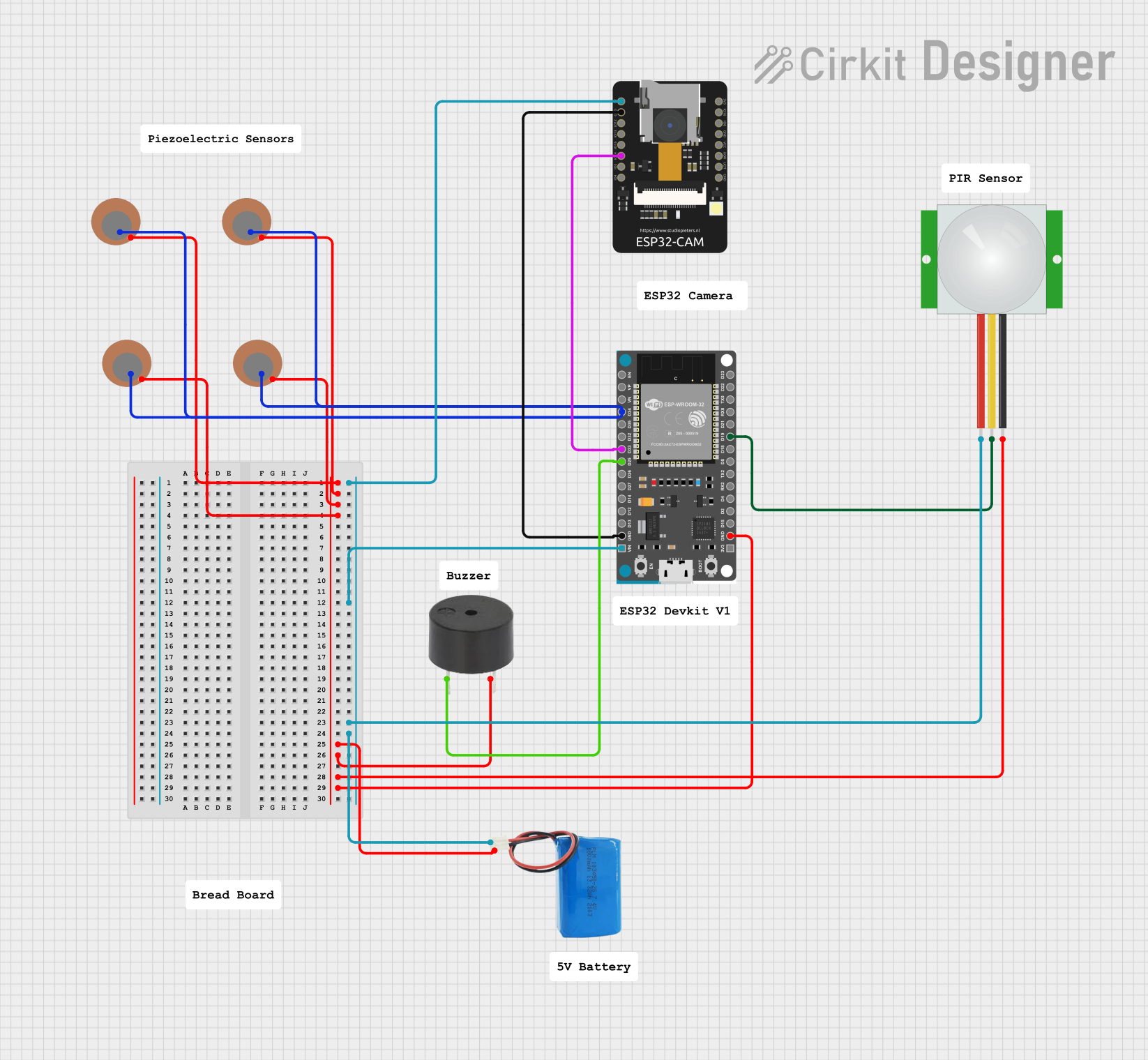
Circuit Documentation
Summary
This circuit is designed to detect motion and vibrations using multiple sensors and respond by capturing a photo with an ESP32-CAM module and sending it via email. The circuit includes multiple piezo sensors, a PIR sensor, a buzzer, an ESP32 Devkit V1 microcontroller, and an ESP32-CAM module. When any sensor detects a signal, the ESP32 will enable the camera to capture a picture and send it to the owner via WiFi.
Component List
Piezo Sensor
- Pins: +, -
- Description: Detects vibrations.
- Purpose in Circuit: Used to detect vibrations and trigger the ESP32.
PIR Sensor
- Pins: VDD, SIG, GND
- Description: Passive Infrared Sensor.
- Purpose in Circuit: Detects motion and triggers the ESP32.
Buzzer
- Pins: PIN, GND
- Description: Emits sound.
- Purpose in Circuit: Provides an audible alert when motion or vibration is detected.
ESP32 Devkit V1
- Pins: 3V3, GND, D15, D2, D4, RX2, TX2, D5, D18, D19, D21, RX0, TX0, D22, D23, EN, VP, VN, D34, D35, D32, D33, D25, D26, D27, D14, D12, D13, VIN
- Description: Microcontroller.
- Purpose in Circuit: Central control unit that processes sensor inputs and controls the camera and buzzer.
ESP32-CAM
- Pins: 5V, GND, IO12, IO13, IO15, IO14, IO2, IO4, VOT, VOR, VCC, IO0, IO16, 3V3
- Description: Camera module.
- Purpose in Circuit: Captures photos when triggered by the ESP32 Devkit V1.
5V Battery
- Pins: positive, negative
- Description: Power source.
- Purpose in Circuit: Provides power to the circuit.
Wiring Details
Piezo Sensor
- Pin + connected to ESP32 Devkit V1 D34
- Pin - connected to 5V Battery negative
Piezo Sensor
- Pin + connected to ESP32 Devkit V1 D34
- Pin - connected to 5V Battery negative
Piezo Sensor
- Pin + connected to ESP32 Devkit V1 D34
- Pin - connected to 5V Battery negative
Piezo Sensor
- Pin + connected to ESP32 Devkit V1 D34
- Pin - connected to 5V Battery negative
PIR Sensor
- Pin VDD connected to 5V Battery positive
- Pin SIG connected to ESP32 Devkit V1 D19
- Pin GND connected to 5V Battery negative
Buzzer
- Pin PIN connected to ESP32 Devkit V1 D25
- Pin GND connected to 5V Battery negative
ESP32 Devkit V1
- Pin VIN connected to 5V Battery positive
- Pin GND connected to 5V Battery negative
- Pin D19 connected to PIR Sensor SIG
- Pin D25 connected to Buzzer PIN
- Pin D34 connected to Piezo Sensor +
ESP32-CAM
- Pin 5V connected to 5V Battery positive
- Pin GND connected to ESP32 Devkit V1 GND
- Pin IO14 connected to ESP32 Devkit V1 D33
5V Battery
- Pin positive connected to ESP32 Devkit V1 VIN, PIR Sensor VDD, and ESP32-CAM 5V
- Pin negative connected to Piezo Sensor -, Buzzer GND, PIR Sensor GND, and ESP32 Devkit V1 GND
Code Documentation
/*
 * This Arduino Sketch is designed for an ESP32 Devkit V1 microcontroller.
 * The circuit includes multiple piezo sensors, a PIR sensor, a buzzer, and
 * an ESP32-CAM module. When any sensor detects a signal, the ESP32 will
 * enable the camera to capture a picture and send it to the owner via WiFi.
 */

#include <WiFi.h>
#include <ESP32_MailClient.h>

// WiFi credentials
const char* ssid = "your_SSID";
const char* password = "your_PASSWORD";

// Email credentials
#define SMTP_HOST "smtp.your-email.com"
#define SMTP_PORT 465
#define AUTHOR_EMAIL "your-email@domain.com"
#define AUTHOR_PASSWORD "your-email-password"
#define RECIPIENT_EMAIL "recipient-email@domain.com"

// Pin definitions
#define PIR_PIN 15
#define BUZZER_PIN 12
#define PIEZO_PIN1 2
#define PIEZO_PIN2 4
#define PIEZO_PIN3 5
#define PIEZO_PIN4 18

// Camera settings
#define CAMERA_MODEL_AI_THINKER
#include "camera_pins.h"

void setup() {
  Serial.begin(115200);
  pinMode(PIR_PIN, INPUT);
  pinMode(BUZZER_PIN, OUTPUT);
  pinMode(PIEZO_PIN1, INPUT);
  pinMode(PIEZO_PIN2, INPUT);
  pinMode(PIEZO_PIN3, INPUT);
  pinMode(PIEZO_PIN4, INPUT);

  // Connect to WiFi
  WiFi.begin(ssid, password);
  while (WiFi.status() != WL_CONNECTED) {
    delay(1000);
    Serial.println("Connecting to WiFi...");
  }
  Serial.println("Connected to WiFi");

  // Initialize camera
  camera_config_t config;
  config.ledc_channel = LEDC_CHANNEL_0;
  config.ledc_timer = LEDC_TIMER_0;
  config.pin_d0 = Y2_GPIO_NUM;
  config.pin_d1 = Y3_GPIO_NUM;
  config.pin_d2 = Y4_GPIO_NUM;
  config.pin_d3 = Y5_GPIO_NUM;
  config.pin_d4 = Y6_GPIO_NUM;
  config.pin_d5 = Y7_GPIO_NUM;
  config.pin_d6 = Y8_GPIO_NUM;
  config.pin_d7 = Y9_GPIO_NUM;
  config.pin_xclk = XCLK_GPIO_NUM;
  config.pin_pclk = PCLK_GPIO_NUM;
  config.pin_vsync = VSYNC_GPIO_NUM;
  config.pin_href = HREF_GPIO_NUM;
  config.pin_sscb_sda = SIOD_GPIO_NUM;
  config.pin_sscb_scl = SIOC_GPIO_NUM;
  config.pin_pwdn = PWDN_GPIO_NUM;
  config.pin_reset = RESET_GPIO_NUM;
  config.pin_xclk = XCLK_GPIO_NUM;
  config.xclk_freq_hz = 20000000;
  config.pixel_format = PIXFORMAT_JPEG;
  config.frame_size = FRAMESIZE_UXGA;
  config.jpeg_quality = 10;
  config.fb_count = 1;

  // Camera init
  esp_err_t err = esp_camera_init(&config);
  if (err != ESP_OK) {
    Serial.printf("Camera init failed with error 0x%x", err);
    return;
  }
}

void loop() {
  if (digitalRead(PIR_PIN) == HIGH || digitalRead(PIEZO_PIN1) == HIGH ||
      digitalRead(PIEZO_PIN2) == HIGH || digitalRead(PIEZO_PIN3) == HIGH ||
      digitalRead(PIEZO_PIN4) == HIGH) {
    digitalWrite(BUZZER_PIN, HIGH);
    captureAndSendPhoto();
    delay(10000); // Wait 10 seconds before next capture
    digitalWrite(BUZZER_PIN, LOW);
  }
}

void captureAndSendPhoto() {
  camera_fb_t * fb = NULL;
  fb = esp_camera_fb_get();
  if (!fb) {
    Serial.println("Camera capture failed");
    return;
  }

  // Send email with photo
  SMTPSession smtp;
  smtp.debug(1);
  smtp.callback(smtpCallback);
  smtp.setLogin(SMTP_HOST, SMTP_PORT, AUTHOR_EMAIL, AUTHOR_PASSWORD);
  smtp.setSender("ESP32-CAM", AUTHOR_EMAIL);
  smtp.addRecipient(RECIPIENT_EMAIL);
  smtp.setPriority("High");
  smtp.setSubject("Intruder Alert");
  smtp.setMessage("Motion detected! See attached photo.", false);
  smtp.addAttachBinary("photo.jpg", fb->buf, fb->len);
  if (!MailClient.sendMail(&smtp)) {
    Serial.println("Error sending Email, " + smtp.errorReason());
  }
  esp_camera_fb_return(fb);
}

void smtpCallback(SMTP_Status status) {
  Serial.println(status.info());
  if (status.success()) {
    Serial.println("Email sent successfully");
  }
}
This documentation provides a comprehensive overview of the circuit, including a summary, detailed component list, wiring details, and the embedded code used in the ESP32 Devkit V1 microcontroller.