
Arduino Nano-Controlled RF Signal Transmitter with Pushbutton Activation
View and Edit Project In Cirkit Designer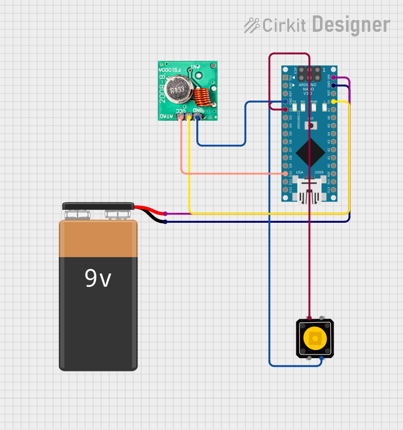
Circuit Documentation
Summary of the Circuit
This circuit is designed to interface an Arduino Nano with a momentary push button switch and an FS1000A 433MHz RF transmitter. The Arduino Nano is powered by a 9V battery and is programmed to read the state of the push button switch. When the button is pressed, the Arduino sends a signal through the RF transmitter. The circuit is simple and is likely used for wireless control applications where a signal is sent remotely upon a button press.
Component List
Pushbutton
- Description: A standard pushbutton with four pins.
- Pins: Pin 3 (out), Pin 4 (out), Pin 1 (in), Pin 2 (in).
9V Battery
- Description: A 9-volt battery providing the power source for the circuit.
- Pins: Negative (-), Positive (+).
Momentary Push Button Switch
- Description: A momentary push button switch that closes the circuit when pressed.
- Pins: 1, 3, 2, 4.
Arduino Nano
- Description: A compact microcontroller board based on the ATmega328P.
- Pins: D1/TX, D0/RX, RESET, GND, D2, D3, D4, D5, D6, D7, D8, D9, D10, D11/MOSI, D12/MISO, VIN, 5V, A7, A6, A5, A4, A3, A2, A1, A0, AREF, 3V3, D13/SCK.
FS1000A 433MHz RF Transmitter
- Description: A simple wireless transmitter module that operates at 433MHz.
- Pins: DATA, VCC, GND, ANT.
Wiring Details
9V Battery
- Negative (-) connected to Arduino Nano GND.
- Positive (+) connected to Arduino Nano VIN.
Momentary Push Button Switch
- Pin 1 connected to Arduino Nano D2.
- Pin 4 connected to Arduino Nano GND.
Arduino Nano
- GND connected to 9V Battery Negative (-) and Momentary Push Button Switch Pin 4.
- VIN connected to 9V Battery Positive (+).
- D2 connected to Momentary Push Button Switch Pin 1.
- D10 connected to FS1000A 433MHz RF Transmitter DATA.
- 5V connected to FS1000A 433MHz RF Transmitter VCC.
FS1000A 433MHz RF Transmitter
- DATA connected to Arduino Nano D10.
- VCC connected to Arduino Nano 5V.
- GND connected to Arduino Nano GND.
Documented Code
// Code for Arduino Nano
const int buttonPin = 2; // Pin connected to the button
const int rfDataPin = 10; // Pin connected to the RF Transmitter DATA pin

void setup() {
  pinMode(buttonPin, INPUT_PULLUP); // Set button pin as input with internal pull-up resistor
  pinMode(rfDataPin, OUTPUT); // Set RF Transmitter DATA pin as output
}

void loop() {
  int buttonState = digitalRead(buttonPin); // Read the state of the button

  if (buttonState == LOW) { // Check if the button is pressed
    digitalWrite(rfDataPin, HIGH); // Send a signal through the RF Transmitter
  } else {
    digitalWrite(rfDataPin, LOW); // Stop sending the signal
  }
}
This code is written for the Arduino Nano and is responsible for reading the state of the momentary push button switch. When the button is pressed, the code sets the RF transmitter's DATA pin high, sending a signal. When the button is released, the DATA pin is set low, stopping the signal transmission. The button pin is configured with an internal pull-up resistor, which means the button is active-low (it reads LOW when pressed).