Wi-Fi Enabled Environmental Monitoring System with Interactive Controls
Circuit Documentation
Summary
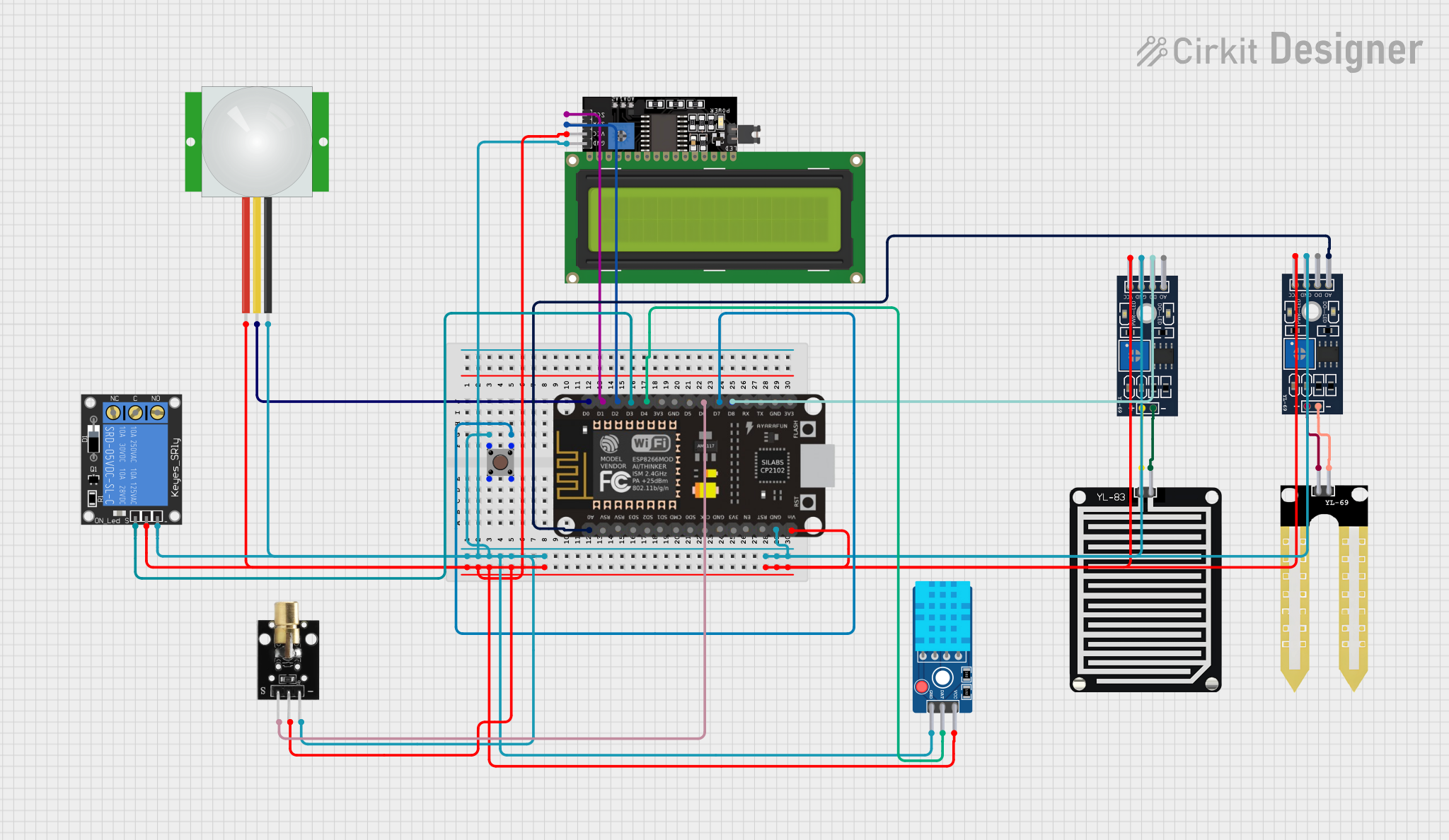
The circuit in question appears to be a multi-sensor system with an ESP8266 NodeMCU microcontroller at its core. It includes a variety of sensors and modules, such as a PIR motion sensor, soil moisture sensors, a temperature and humidity sensor, a laser emitter, and a relay for controlling power to an external device. The system also features a pushbutton for user input and an LCD display for output. The sensors and modules are interfaced with the ESP8266 NodeMCU, which likely serves as the central processing unit, handling sensor data, controlling the relay, and managing user interaction through the pushbutton and display.
Component List
PIR Sensor
- Pins: VDD, SIG, GND
- Description: A motion detection sensor that outputs a signal when motion is detected.
ESP8266 NodeMCU
- Pins: D0-D8, RX, TX, A0, RSV, SD3, SD2, SD1, CMD, SD0, CLK, EN, RST, VIN, 3V3, GND
- Description: A Wi-Fi enabled microcontroller used for controlling the various components in the circuit.
Pushbutton
- Pins: Pin 1 (in), Pin 2 (in), Pin 3 (out), Pin 4 (out)
- Description: A simple pushbutton switch used for user input.
LCD Display 16x4 I2C
- Pins: SCL, SDA, VCC, GND
- Description: An alphanumeric liquid crystal display for showing information to the user.
YL-69 Module LM393 (Two Instances)
- Pins: A0, DO, GND, VCC, -, +
- Description: A soil moisture sensor module that can output both analog and digital signals.
YL-69 Sonda
- Pins: +, -
- Description: The probe part of the soil moisture sensor that measures the moisture level.
YL-83 Sonda
- Pins: +, -
- Description: A probe that is likely part of a rain detection or similar type of sensor.
DHT11 Sensor V2
- Pins: GND, DAT, VCC
- Description: A sensor for measuring temperature and humidity.
KY-008 Laser Emitter
- Pins: SIG, 5v, GND
- Description: A module that emits a laser beam when powered.
1-Channel Relay (5V 10A)
- Pins: NC, signal, C, power, NO, ground
- Description: An electromechanical switch that allows the microcontroller to control high power devices.
Wiring Details
PIR Sensor
- VDD: Connected to power supply.
- SIG: Connected to ESP8266 NodeMCU D0.
- GND: Connected to common ground.
ESP8266 NodeMCU
- D0: Connected to PIR Sensor SIG.
- D1: Connected to LCD Display SCL.
- D2: Connected to LCD Display SDA.
- D3: Connected to 1-Channel Relay signal.
- D4: Connected to DHT11 Sensor DAT.
- D6: Connected to KY-008 Laser Emitter SIG.
- D7: Connected to Pushbutton Pin 3 (out).
- D8: Connected to YL-69 Module LM393 DO.
- A0: Connected to YL-69 Module LM393 A0.
- GND: Connected to common ground.
- VIN: Connected to power supply.
Pushbutton
- Pin 1 (in): Connected to common ground.
- Pin 3 (out): Connected to ESP8266 NodeMCU D7.
LCD Display 16x4 I2C
- SCL: Connected to ESP8266 NodeMCU D1.
- SDA: Connected to ESP8266 NodeMCU D2.
- VCC: Connected to power supply.
- GND: Connected to common ground.
YL-69 Module LM393
- A0: Connected to ESP8266 NodeMCU A0 (for one instance).
- DO: Connected to ESP8266 NodeMCU D8 (for one instance).
- GND: Connected to common ground.
- VCC: Connected to power supply.
- -: Connected to YL-69 Sonda - (for one instance).
- +: Connected to YL-69 Sonda + (for one instance).
YL-69 Sonda
- +: Connected to YL-69 Module LM393 +.
- -: Connected to YL-69 Module LM393 -.
YL-83 Sonda
- +: Connected to YL-69 Module LM393 + (for the second instance).
- -: Connected to YL-69 Module LM393 - (for the second instance).
DHT11 Sensor V2
- GND: Connected to common ground.
- DAT: Connected to ESP8266 NodeMCU D4.
- VCC: Connected to power supply.
KY-008 Laser Emitter
- SIG: Connected to ESP8266 NodeMCU D6.
- 5v: Connected to power supply.
- GND: Connected to common ground.
1-Channel Relay (5V 10A)
- signal: Connected to ESP8266 NodeMCU D3.
- power: Connected to power supply.
- ground: Connected to common ground.
Documented Code
No code has been provided for the microcontroller. The expected functionality would include reading sensor data, controlling the relay, responding to button presses, and updating the display. Without the code, we cannot document the specific behavior of the microcontroller in this circuit.