
Arduino UNO R4 WiFi Controlled Dissolved Ozone Monitoring System with RS485 and LCD Display
View and Edit Project In Cirkit Designer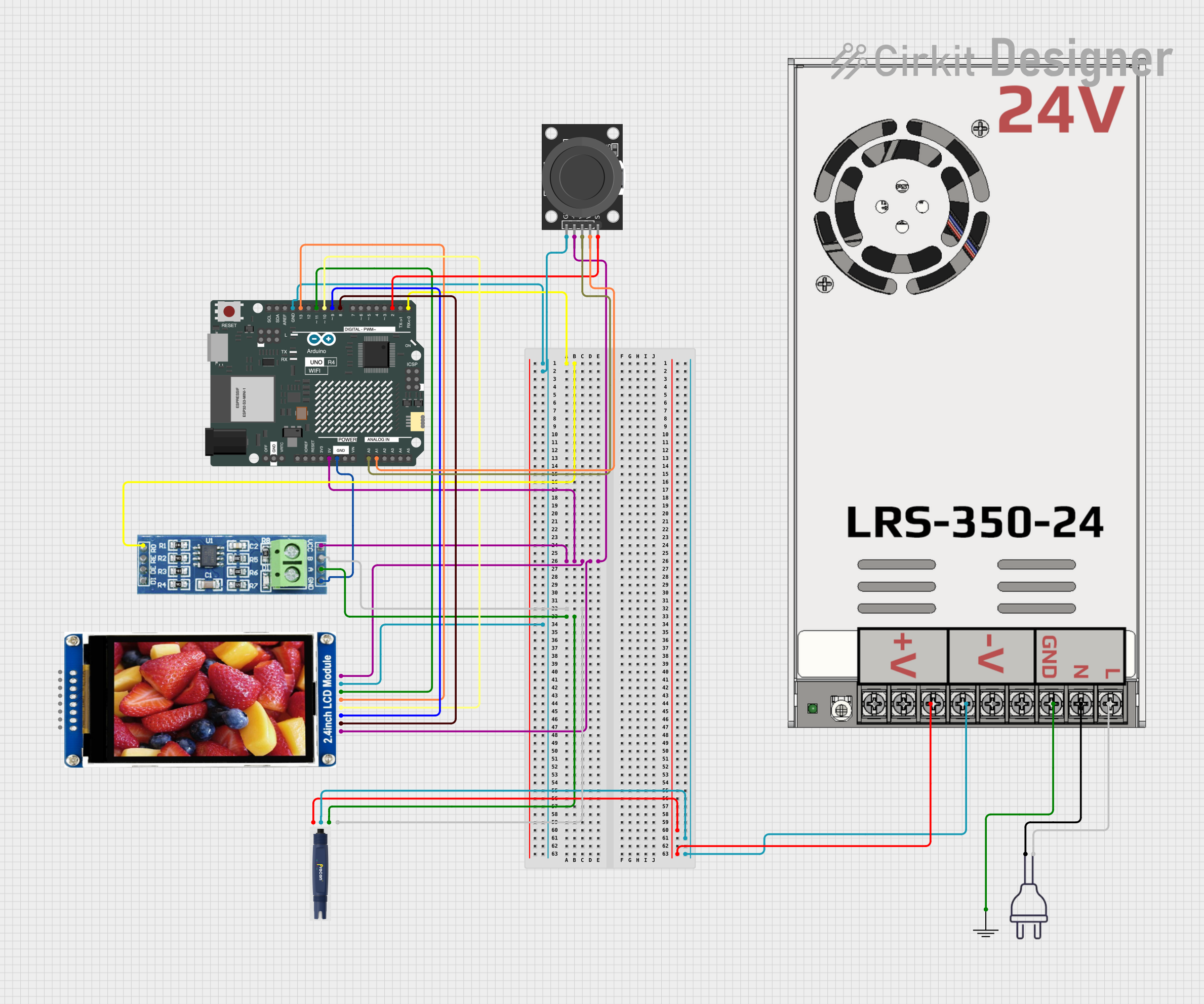
Circuit Documentation
Summary
This circuit integrates various components to perform a specific function. The core of the circuit is an Arduino UNO R4 WiFi, which is responsible for controlling the other components, including an RS485 module, a power supply unit (MW LRS-350-24), a dissolved ozone sensor, a 2.4" LCD Module, and a KY-023 Dual Axis Joystick Module. The Arduino communicates with the dissolved ozone sensor via the RS485 module to read ozone levels and displays the data on the LCD. The joystick allows for user interaction with the display. The power supply unit provides the necessary voltage levels for the sensor and other components.
Component List
- Arduino UNO R4 WiFi: A microcontroller board based on the ATmega328, which includes WiFi capabilities for network connectivity.
- RS485 Module: A module used for high-speed, long-distance data communication.
- MW LRS-350-24 Power Supply: A 24V power supply unit that provides power to the circuit.
- Power 220V: Represents the main AC power source for the circuit.
- Ground (GND): A common ground reference point for the circuit.
- Dissolved Ozone Sensor: A sensor that measures the concentration of dissolved ozone in a medium.
- 2.4" LCD Module: A display module used for visualizing data and information from the microcontroller.
- KY-023 Dual Axis Joystick Module: A joystick input device that provides user control.
Wiring Details
Arduino UNO R4 WiFi
D0/RXconnected to RS485 ModuleRO5Vconnected to:- KY-023 Dual Axis Joystick Module
+5V - 2.4" LCD Module
VCCandBL - RS485 Module
VCC
- KY-023 Dual Axis Joystick Module
GNDconnected to:- KY-023 Dual Axis Joystick Module
GND - 2.4" LCD Module
GND - RS485 Module
GND
- KY-023 Dual Axis Joystick Module
A0connected to KY-023 Dual Axis Joystick ModuleVRxA1connected to KY-023 Dual Axis Joystick ModuleVRyD2connected to KY-023 Dual Axis Joystick ModuleSWD8connected to 2.4" LCD ModuleRSTD9connected to 2.4" LCD ModuleDCD10connected to 2.4" LCD ModuleCSD11connected to 2.4" LCD ModuleDIND13connected to 2.4" LCD ModuleCLK
RS485 Module
ROconnected to Arduino UNO R4 WiFiD0/RXVCCconnected to Arduino UNO R4 WiFi5VGNDconnected to Arduino UNO R4 WiFiGNDBconnected to Dissolved Ozone Sensor485BAconnected to Dissolved Ozone Sensor485a
MW LRS-350-24 Power Supply
+24V Outputconnected to Dissolved Ozone Sensor9~24v+-24V Outputconnected to Dissolved Ozone Sensor9~24v-GNDconnected to Ground (GND)GNDNconnected to Power 220Vneutral wireLconnected to Power 220Vhot wire
Power 220V
neutral wireconnected to MW LRS-350-24 Power SupplyNhot wireconnected to MW LRS-350-24 Power SupplyL
Dissolved Ozone Sensor
9~24v+connected to MW LRS-350-24 Power Supply+24V Output9~24v-connected to MW LRS-350-24 Power Supply-24V Output485Bconnected to RS485 ModuleB485aconnected to RS485 ModuleA
2.4" LCD Module
VCCconnected to Arduino UNO R4 WiFi5VGNDconnected to Arduino UNO R4 WiFiGNDDINconnected to Arduino UNO R4 WiFiD11CLKconnected to Arduino UNO R4 WiFiD13CSconnected to Arduino UNO R4 WiFiD10DCconnected to Arduino UNO R4 WiFiD9RSTconnected to Arduino UNO R4 WiFiD8BLconnected to Arduino UNO R4 WiFi5V
KY-023 Dual Axis Joystick Module
GNDconnected to Arduino UNO R4 WiFiGND+5Vconnected to Arduino UNO R4 WiFi5VVRxconnected to Arduino UNO R4 WiFiA0VRyconnected to Arduino UNO R4 WiFiA1SWconnected to Arduino UNO R4 WiFiD2
Documented Code
The code provided is an Arduino sketch designed to interface with a dissolved ozone sensor via RS485 and display the sensor readings on a 2.4" LCD module. The Arduino UNO R4 WiFi is used as the microcontroller. The sensor data is read from the RS485 module and displayed on the LCD. Additionally, a joystick module is used to navigate the display.
The sketch includes the necessary libraries for SPI communication, the Adafruit GFX library for graphics operations, and the Adafruit ILI9341 library for the LCD module. The code initializes the serial communication, LCD, RS485 communication, and joystick. In the main loop, the sensor data is read and displayed on the LCD, and the joystick values are read and displayed as well.
The code also contains a detailed section of the Adafruit GFX library, which provides a common set of graphics primitives (points, lines, circles, etc.) and needs to be paired with a hardware-specific library for each display device.
Note: The code provided in the input is extensive and includes implementation details for the Adafruit GFX library. For brevity, the documentation here summarizes the purpose and high-level functionality of the code. The full code should be referred to for detailed implementation and functions.