Cirkit Designer
Your all-in-one circuit design IDE
Home /
Project Documentation
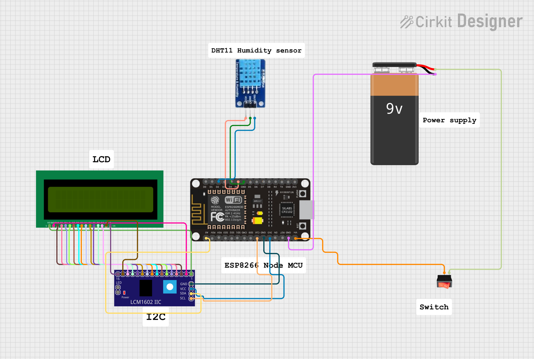
ESP8266 Battery-Powered IoT Weather Station with DHT11 and LCD Display
Circuit Documentation
Summary
This circuit is designed to monitor temperature, humidity, and battery level using an ESP8266 NodeMCU microcontroller. The circuit includes a DHT11 sensor for temperature and humidity measurements, a 16x2 LCD display for visual output, and a 9V battery for power supply. The ESP8266 NodeMCU is programmed to send data to a Blynk IoT platform and display information on an OLED screen.
Component List
Rocker Switch
- Description: A simple on/off switch to control the power supply.
- Pins:
output,input
DHT11
- Description: A digital temperature and humidity sensor.
- Pins:
DATA,GND,VCC
LCM1602 IIC
- Description: An I2C interface for 16x2 LCD displays.
- Pins:
GND,VCC,SDA,SCL,D6,D7,A,K,VSS,VDD,V0,RS,D2,D3,D4,D5,RW,E,D0,D1,LED_A,LED_B
16x2 LCD
- Description: A 16x2 character LCD display.
- Pins:
VSS,VDD,V0,RS,RW,E,D1,D0,D2,D3,D4,D6,D5,D7,A,K
ESP8266 NodeMCU
- Description: A Wi-Fi enabled microcontroller.
- Pins:
D0,D1,D2,D3,D4,3V3,GND,D5,D6,D7,D8,RX,TX,A0,RSV,SD3,SD2,SD1,CMD,SD0,CLK,EN,RST,VIN
9V Battery
- Description: A 9V battery for power supply.
- Pins:
-,+
Wiring Details
Rocker Switch
- output connected to VIN of ESP8266 NodeMCU
- input connected to + of 9V Battery
DHT11
- DATA connected to D2 of ESP8266 NodeMCU
- VCC connected to 3V3 of ESP8266 NodeMCU
- GND connected to GND of ESP8266 NodeMCU
LCM1602 IIC
- SDA connected to A0 of ESP8266 NodeMCU
- SCL connected to CLK of ESP8266 NodeMCU
- GND connected to GND of ESP8266 NodeMCU
- VCC connected to 3V3 of ESP8266 NodeMCU
16x2 LCD
- VSS connected to VSS of LCM1602 IIC
- VDD connected to VDD of LCM1602 IIC
- V0 connected to V0 of LCM1602 IIC
- RS connected to RS of LCM1602 IIC
- RW connected to RW of LCM1602 IIC
- E connected to E of LCM1602 IIC
- D1 connected to D1 of LCM1602 IIC
- D0 connected to D0 of LCM1602 IIC
- D2 connected to D2 of LCM1602 IIC
- D3 connected to D3 of LCM1602 IIC
- D4 connected to D4 of LCM1602 IIC
- D6 connected to D6 of LCM1602 IIC
- D5 connected to D5 of LCM1602 IIC
- D7 connected to D7 of LCM1602 IIC
- A connected to A of LCM1602 IIC
- K connected to K of LCM1602 IIC
ESP8266 NodeMCU
- GND connected to - of 9V Battery
Code Documentation
ESP8266 NodeMCU Code
/*
  -----------------------
  ESP8266 Monitor its Own Battery Level using IoT
  -----------------------
  Website: https://iotprojectsideas.com/
  -----------------------
*/

// Fill-in information from your Blynk Template here
#define BLYNK_TEMPLATE_ID "TMPxxx-xxx-xxx"
#define BLYNK_DEVICE_NAME "Smart IoT"

#define BLYNK_FIRMWARE_VERSION        "0.1.0"

#define BLYNK_PRINT Serial
//#define BLYNK_DEBUG

#define APP_DEBUG

// Uncomment your board, or configure a custom board in Settings.h
//#define USE_SPARKFUN_BLYNK_BOARD
#define USE_NODE_MCU_BOARD
//#define USE_WITTY_CLOUD_BOARD
//#define USE_WEMOS_D1_MINI

#include "BlynkEdgent.h"
#include <DHT.h>
#include <Adafruit_GFX.h>
#include <Adafruit_SSD1306.h>

#define SCREEN_WIDTH 128    // OLED display width, in pixels
#define SCREEN_HEIGHT 64    // OLED display height, in pixels
#define OLED_RESET -1       // Reset pin # (or -1 if sharing Arduino reset pin)

#define DHTTYPE DHT22     // DHT 22
#define DHTPIN D4 //DHT22 Pin D4(GPIO 2)

DHT dht(DHTPIN, DHTTYPE);
Adafruit_SSD1306 display(SCREEN_WIDTH, SCREEN_HEIGHT, &Wire, OLED_RESET);

float voltage;
int bat_percentage;
int analogInPin  = A0;    // Analog input pin
int sensorValue;
float calibration = 0.40; // Check Battery voltage using multimeter & add/subtract the value

void setup()
{
  Serial.begin(115200);
  delay(100);

  BlynkEdgent.begin();

  dht.begin();
  display.begin(SSD1306_SWITCHCAPVCC, 0x3C); //initialize with the I2C addr 0x3C (128x64)
  display.clearDisplay();
  display.setTextColor(WHITE);

  delay(100);
}

void loop() {
  BlynkEdgent.run();
  float t = dht.readTemperature();
  float h = dht.readHumidity();

  sensorValue = analogRead(analogInPin);
  voltage = (((sensorValue * 3.3) / 1024) * 2 + calibration); //multiply by two as voltage divider network is 100K & 100K Resistor

  bat_percentage = mapfloat(voltage, 2.8, 4.2, 0, 100); //2.8V as Battery Cut off Voltage & 4.2V as Maximum Voltage

  if (bat_percentage >= 100)
  {
    bat_percentage = 100;
  }
  if (bat_percentage <= 0)
  {
    bat_percentage = 1;
  }

  //send data to blynk
  Blynk.virtualWrite(V1, t); //for Temperature
  Blynk.virtualWrite(V2, h); //for Humidity
  Blynk.virtualWrite(V3, voltage);  // for battery voltage
  Blynk.virtualWrite(V4, bat_percentage);  // for battery percentage

  //Print data on serial monitor
  Serial.print("Temperature: ");
  Serial.print(t);
  Serial.println(" *C");

  Serial.print("Humidity: ");
  Serial.print(h);
  Serial.println(" %");

  Serial.print("Analog Value = ");
  Serial.println(sensorValue);
  Serial.print("Output Voltage = ");
  Serial.println(voltage);
  Serial.print("Battery Percentage = ");
  Serial.println(bat_percentage);

  Serial.println();
  Serial.println("****************************");
  Serial.println();
  delay(1000);

  if (bat_percentage <=30)
  {
    Serial.println("Battery level below 30%, Charge battery on time");
    //send notification
    Blynk.logEvent("battery_low", "Battery is getting low.... Plugin to charge") ;
    delay(500);
  }

  // display temperature on OLED
  display.clearDisplay();
  display.setTextColor(WHITE);
  display.setTextSize(1);
  display.setCursor(0, 0);
  display.print("Temperature: ");
  display.setTextSize(2);
  display.setCursor(0, 10);
  display.print(t);
  display.print(" ");
  display.setTextSize(1);
  display.cp