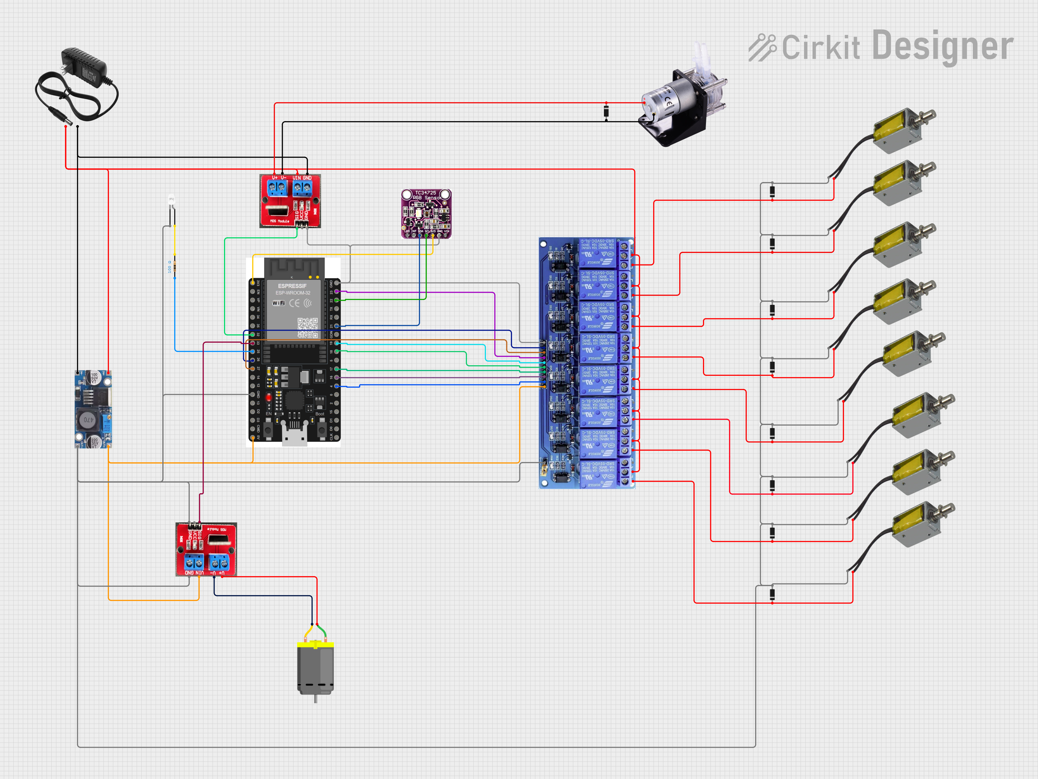
ESP32-Controlled Fluid Dispensing System with Color Sensing and PWM Motor Control

Circuit Documentation
Summary
The circuit in question appears to be a control system that utilizes an ESP32 microcontroller to manage various peripherals including a TCS3472 color light-to-digital converter, an 8-channel relay module, several push-pull solenoids, a peristaltic pump, a DC motor, and a step-down buck converter. The ESP32 is responsible for interfacing with the TCS3472 sensor and controlling the relays which in turn drive the solenoids, pump, and motor. Power management is handled by the step-down buck converter and a 12V power supply. Protection diodes are used across the inductive loads to prevent back EMF damage. An LED with a current-limiting resistor is also part of the circuit for indication purposes.
Component List
Step down Buck Converter
- Converts higher voltage to a lower voltage.
- Pins: IN +, IN - GND, OUT +, OUT - GND
12V Power Supply
- Provides a 12V power source for the circuit.
- Pins: +, -
Diode
- Allows current to flow in one direction, used for protection against back EMF.
- Pins: cathode, anode
8 Channel Relay JD-VCC
- Allows the ESP32 to control higher power devices.
- Pins: JD-VCC, VCC, GND, In1 to In8, In1_NC to In8_NC, IN1_COM to IN8_COM, IN1_NO to IN8_NO
Push Pull Solenoid
- Actuates when energized, used for mechanical movements.
- Pins: +ve, -ve
ESP32 38 PINS
- A microcontroller with WiFi and Bluetooth capabilities.
- Pins: GND, 23, 22/SCL, 1, 2, 21/SDA, 19, 18, 5, 17/TX2, 16/RX2, 4, 0, 15, D1, D0, CLK, 3V3, EN, VP, VN, 34, 35, 32, 33, 25, 26, 27, 14, 12, 13, D2, D3, 11, 5V/VIN
IRF520 PWM
- A MOSFET module that allows the ESP32 to control high-power devices.
- Pins: V+, V-, Vin, GND, SIG, Vcc
Peristaltic Pump
- A type of pump used for precise fluid handling.
- Pins: +, -
TCS3472 COLOR LIGHT-TO-DIGITAL CONVERTER with IR FILTER
- A color sensor that converts light input to digital signals.
- Pins: LED, INT, SDA, SCL, 3V3, GND, VIN
LED: Two Pin (white)
- A white light-emitting diode for indication.
- Pins: cathode, anode
Resistor
- Limits current, used here to protect the LED.
- Pins: pin1, pin2
- Resistance: 100 Ohms
DC Motor
- Converts electrical energy into mechanical energy.
- Pins: pin 1, pin 2
Wiring Details
Step down Buck Converter
- IN +: Connected to the 12V power supply (+)
- IN - GND: Connected to the 12V power supply (-) and GND of other components
- OUT +: Connected to VCC of the 8 Channel Relay, Vin of the ESP32 (5V/VIN), and Vin of the IRF520 PWM
- OUT - GND: Connected to GND of other components
12V Power Supply
- +: Connected to IN + of the Step down Buck Converter and COM pins of the 8 Channel Relay
- -: Connected to IN - GND of the Step down Buck Converter
Diode
- Multiple diodes are used across the circuit, typically with the cathode connected to the positive side of a load and the anode connected to the negative side or GND to protect against back EMF.
8 Channel Relay JD-VCC
- JD-VCC: Not specified in the net list
- VCC: Connected to OUT + of the Step down Buck Converter
- GND: Connected to GND of other components
- In1 to In8: Controlled by various GPIO pins of the ESP32
- IN1_COM to IN8_COM: Connected to + of the 12V power supply
- IN1_NO to IN8_NO: Connected to the positive side of various solenoids
Push Pull Solenoid
- +ve: Connected to the NO pins of the 8 Channel Relay and the cathode of diodes
- -ve: Connected to GND of the circuit
ESP32 38 PINS
- GND: Connected to GND of other components
- 23, 19, 18, 17/TX2, 16/RX2, 4: Connected to In3 to In8 of the 8 Channel Relay
- 22/SCL, 21/SDA: Connected to SCL and SDA of the TCS3472 sensor
- 32, 33: Connected to SIG of the IRF520 PWM modules
- 25, 26, 27: Connected to various components (not fully specified)
- 3V3: Connected to 3V3 of the TCS3472 sensor
- 5V/VIN: Connected to OUT + of the Step down Buck Converter
IRF520 PWM
- V+: Connected to the positive side of the Peristaltic Pump and DC Motor
- V-: Connected to the negative side of the Peristaltic Pump and DC Motor
- Vin: Connected to OUT + of the Step down Buck Converter and + of the 12V power supply
- GND: Connected to GND of the circuit
- SIG: Controlled by GPIO pins 32 and 33 of the ESP32
- Vcc: Not specified in the net list
Peristaltic Pump
- +: Connected to V+ of the IRF520 PWM and the cathode of a diode
- -: Connected to V- of the IRF520 PWM and the anode of a diode
TCS3472 COLOR LIGHT-TO-DIGITAL CONVERTER with IR FILTER
- LED: Not specified in the net list
- INT: Not specified in the net list
- SDA: Connected to 21/SDA of the ESP32
- SCL: Connected to 22/SCL of the ESP32
- 3V3: Connected to 3V3 of the ESP32
- GND: Connected to GND of the circuit
- VIN: Not specified in the net list
LED: Two Pin (white)
- cathode: Connected to the anode of a diode and -ve of a solenoid
- anode: Connected to pin2 of the resistor
Resistor
- pin1: Connected to GPIO 25 of the ESP32
- pin2: Connected to the anode of the LED
DC Motor
- pin 1: Connected to V+ of the IRF520 PWM
- pin 2: Connected to V- of the IRF520 PWM
Documented Code
No code was provided in the input, so this section cannot be completed. If code is provided at a later time, it should be documented here with explanations of how the code interacts with the hardware components listed above.