Arduino-Controlled Servo Positioning with Joystick Input
Circuit Documentation
Summary
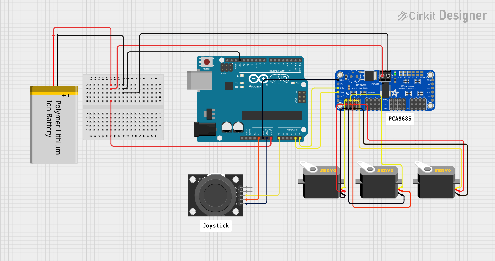
This circuit is designed to control three servo motors using an Arduino UNO microcontroller and an Adafruit PCA9685 PWM Servo Breakout board. The control input is provided by a KY-023 Dual Axis Joystick Module. The servos' positions are determined by the X-axis of the joystick. The circuit is powered by a Polymer Lithium Ion Battery, which supplies power to both the Arduino and the PCA9685 board. The Arduino communicates with the PCA9685 via I2C protocol, using the SDA and SCL lines.
Component List
Polymer Lithium Ion Battery - Generic
- Pins: GND, VCC
- Description: Provides power to the circuit.
Arduino UNO
- Pins: UNUSED, IOREF, Reset, 3.3V, 5V, GND, Vin, A0-A5, SCL, SDA, AREF, D0-D13
- Description: Acts as the central microcontroller unit to process inputs and control outputs.
KY-023 Dual Axis Joystick Module
- Pins: GND, +5V, VRx, VRy, SW
- Description: Provides analog input to control the servos.
Adafruit PCA9685 PWM Servo Breakout
- Pins: 5.0V, GND, PWRIN, PWM0-PWM15, VCC, SDA, SCL, OE
- Description: Drives up to 16 servos with individual 12-bit PWM channels.
Servo (3 instances)
- Pins: gnd, vcc, pulse
- Description: Actuators that are controlled by PWM signals to move to specified positions.
Comment (2 instances)
- Pins: None
- Description: Not applicable to the circuit functionality.
Wiring Details
Polymer Lithium Ion Battery - Generic
- GND connected to GND of Arduino UNO and Adafruit PCA9685 PWM Servo Breakout.
- VCC connected to Vin of Arduino UNO and PWRIN of Adafruit PCA9685 PWM Servo Breakout.
Arduino UNO
- 5V connected to +5V of KY-023 Dual Axis Joystick Module.
- GND connected to GND of KY-023 Dual Axis Joystick Module and Adafruit PCA9685 PWM Servo Breakout.
- A0 connected to VRx of KY-023 Dual Axis Joystick Module.
- A4 (SDA) connected to SDA of Adafruit PCA9685 PWM Servo Breakout.
- A5 (SCL) connected to SCL of Adafruit PCA9685 PWM Servo Breakout.
KY-023 Dual Axis Joystick Module
- +5V connected to 5V of Arduino UNO.
- GND connected to GND of Arduino UNO.
- VRx connected to A0 of Arduino UNO.
Adafruit PCA9685 PWM Servo Breakout
- 5.0V connected to VCC of all Servos.
- GND connected to GND of all Servos and GND of Arduino UNO.
- PWRIN connected to VCC of Polymer Lithium Ion Battery - Generic.
- PWM0-PWM2 connected to pulse of each Servo.
- SDA connected to A4 (SDA) of Arduino UNO.
- SCL connected to A5 (SCL) of Arduino UNO.
Servo (3 instances)
- gnd connected to GND of Adafruit PCA9685 PWM Servo Breakout.
- vcc connected to 5.0V of Adafruit PCA9685 PWM Servo Breakout.
- pulse connected to PWM0, PWM1, and PWM2 of Adafruit PCA9685 PWM Servo Breakout respectively.
Documented Code
#include <Wire.h>
#include <Adafruit_PWMServoDriver.h>

// Create the PWM driver object
Adafruit_PWMServoDriver pwm = Adafruit_PWMServoDriver();

// Joystick and Servo configuration
int joystickX = A0;   // Joystick X-axis connected to A0
int servoMin = 150;   // Minimum pulse length count (out of 4096)
int servoMax = 900;   // Maximum pulse length count (out of 4096)

// Define servo position channels
int servo1Channel = 0; // Servo 1 is connected to channel 0 on PCA9685
int servo2Channel = 1; // Servo 2 is connected to channel 1 on PCA9685
int servo3Channel = 2; // Servo 3 is connected to channel 2 on PCA9685

// Calculate the center position
int centerPos = (servoMin + servoMax) / 2;

// Variables to store the current position of the servos
int currentPos1 = centerPos;
int currentPos2 = centerPos;
int currentPos3 = centerPos;

void setup() {
  // Initialize the I2C communication and the PCA9685
  pwm.begin();
  pwm.setPWMFreq(60); // Analog servos run at ~60 Hz

  // Initialize the joystick pin
  pinMode(joystickX, INPUT);
}

void loop() {
  // Read the joystick value
  int joystickVal = analogRead(joystickX); // Joystick X-axis

  // Map the joystick value to the servo's pulse length range
  int targetPos;

  if (joystickVal < 512) {
    // Map joystick values on the left side to servo positions
    targetPos = map(joystickVal, 0, 512, servoMax, centerPos);
  } else {
    // Map joystick values on the right side to servo positions
    targetPos = map(joystickVal, 512, 1023, centerPos, servoMin);
  }

  // Smoothly move servos toward the target position
  currentPos1 = moveServo(currentPos1, targetPos);
  currentPos2 = moveServo(currentPos2, targetPos);
  currentPos3 = moveServo(currentPos3, targetPos);

  // Set the position for all three servos
  pwm.setPWM(servo1Channel, 0, currentPos1); // Set the position for Servo 1
  pwm.setPWM(servo2Channel, 0, currentPos2); // Set the position for Servo 2
  pwm.setPWM(servo3Channel, 0, currentPos3); // Set the position for Servo 3

  // Add a small delay to control speed
  delay(15);
}

// Function to move the servo smoothly toward the target position
int moveServo(int currentPos, int targetPos) {
  if (currentPos < targetPos) {
    currentPos += 1; // Increment position
  } else if (currentPos > targetPos) {
    currentPos -= 1; // Decrement position
  }
  return currentPos;
}
This code is responsible for reading the joystick's X-axis position and mapping it to the servo's pulse length range. It then smoothly moves each servo to the target position based on the joystick input. The Adafruit_PWMServoDriver library is used to control the PWM signals sent to the servos via the PCA9685 breakout board.