
Arduino UNO and NRF24L01 Wireless Communication Circuit with LED Indicator
View and Edit Project In Cirkit Designer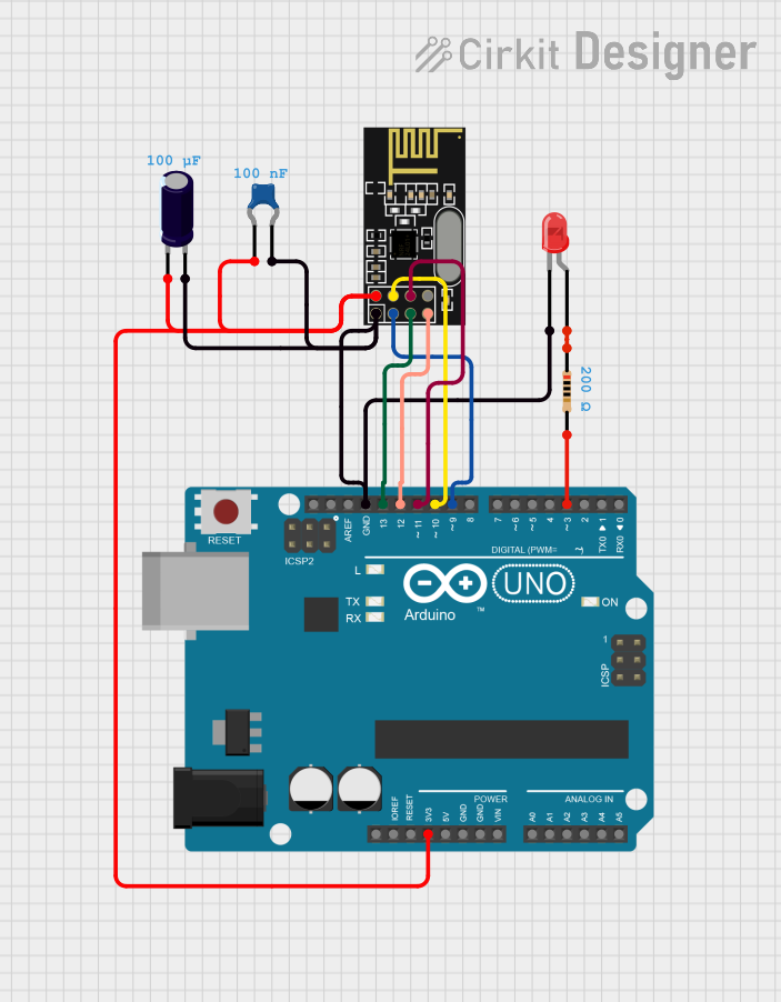
Circuit Documentation
Summary
This circuit integrates an Arduino UNO microcontroller with an NRF24L01 wireless transceiver module. It includes passive components such as a ceramic capacitor, an electrolytic capacitor, a resistor, and a red LED. The capacitors are used for power supply decoupling, while the resistor limits the current to the LED. The NRF24L01 is interfaced with the Arduino UNO for SPI communication and control signals.
Component List
Arduino UNO
- Microcontroller board based on the ATmega328P
- Provides digital I/O pins, analog inputs, and various power outputs
NRF24L01
- 2.4GHz wireless transceiver module
- Interfaces with microcontroller via SPI for wireless communication
Ceramic Capacitor
- Small-value capacitor typically used for noise filtering or decoupling
- Capacitance: 0.1 µF (100 nF)
Electrolytic Capacitor
- Larger-value capacitor used for power supply smoothing
- Capacitance: 100 µF
Resistor
- Passive component used to limit current or divide voltage
- Resistance: 200 Ohms
LED: Two Pin (red)
- Light Emitting Diode that emits red light when forward biased
- Used as an indicator light in circuits
Wiring Details
Arduino UNO
3.3Vconnected to NRF24L01VCC (3V)and Ceramic Capacitorpin0GNDconnected to NRF24L01GND, Electrolytic Capacitor+, Ceramic Capacitorpin1, and LEDcathodeD13connected to NRF24L01SCKD12connected to NRF24L01MISOD11connected to NRF24L01MOSID10connected to NRF24L01CSND9connected to NRF24L01CED3connected to Resistorpin2
NRF24L01
VCC (3V)connected to Arduino UNO3.3Vand Ceramic Capacitorpin0GNDconnected to Arduino UNOGND, Electrolytic Capacitor+, Ceramic Capacitorpin1, and LEDcathodeSCKconnected to Arduino UNOD13MISOconnected to Arduino UNOD12MOSIconnected to Arduino UNOD11CSNconnected to Arduino UNOD10CEconnected to Arduino UNOD9
Ceramic Capacitor
pin0connected to Arduino UNO3.3Vpin1connected to Arduino UNOGND
Electrolytic Capacitor
-connected to NRF24L01VCC (3V)+connected to Arduino UNOGND
Resistor
pin1connected to LEDanodepin2connected to Arduino UNOD3
LED: Two Pin (red)
anodeconnected to Resistorpin1cathodeconnected to Arduino UNOGND
Documented Code
Arduino UNO Code (sketch.ino)
void setup() {
  // put your setup code here, to run once:

}

void loop() {
  // put your main code here, to run repeatedly:

}
Note: The provided code is a template and does not include specific functionality. It should be populated with the setup and loop routines required for the intended operation of the Arduino UNO with the NRF24L01 module.