
Circuit Documentation
Summary
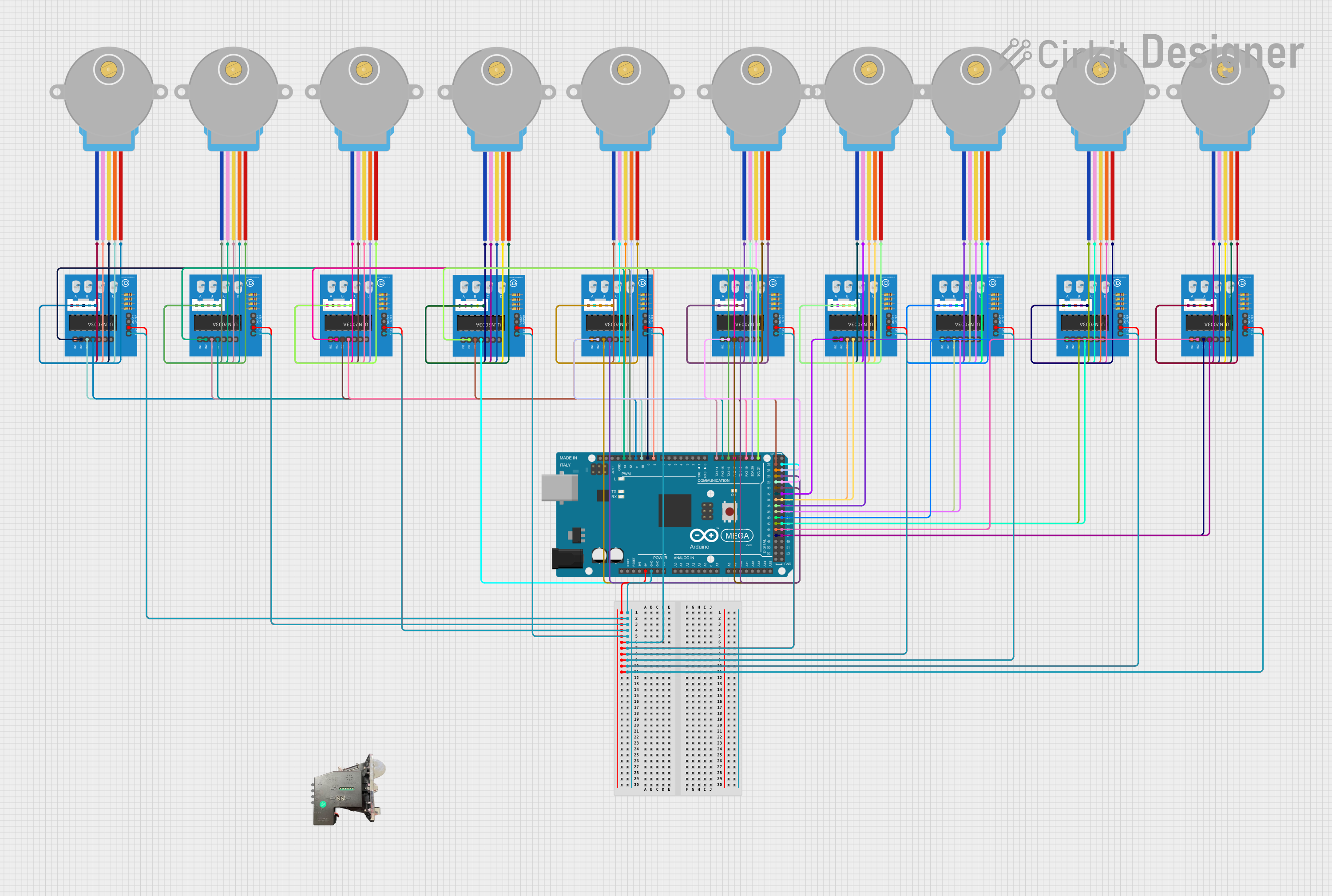
This circuit is designed to control multiple 28BYJ-48 Stepper Motors using ULN2003A breakout boards. The central control unit for the circuit is an Arduino Mega 2560, which provides the necessary digital control signals to the ULN2003A driver boards. Each driver board interfaces with a single stepper motor, allowing for independent control of each motor. The circuit is powered by the 5V output from the Arduino Mega 2560, which is distributed to the ULN2003A boards. Ground connections are also distributed from the Arduino to the driver boards to complete the power circuit.
Component List
- Arduino Mega 2560: A microcontroller board based on the ATmega2560, with numerous digital and analog I/O pins for interfacing with various components and sensors.
- ULN2003A Breakout Board: A board that contains the ULN2003A Darlington transistor array, used for driving stepper motors.
- 28BYJ-48 Stepper Motor: A small, 5-wire, unipolar stepper motor that can be driven by the ULN2003A breakout board.
- Coin Reader: A device that detects and counts coins.
Wiring Details
Arduino Mega 2560
- Digital pins (D21/SCL, D20/SDA, D19/RX1, D18/TX1, D17 PWM/RX2, D16 PWM/TX2, D15/RX3, D14/TX3, D8 PWM, D9 PWM, D10 PWM, D11 PWM, D12 PWM, D13 PWM, D46, D44, D42, D40, D38, D36, D34, D32, D30, D28, D26, D24, D22, D47, D45, D43, D41, D39, D37, D35, D33, D31, D29, D27, D25, D23) are used to send control signals to the ULN2003A breakout boards.
- 5V pin is used to supply power to the ULN2003A breakout boards.
- GND pin is used to provide a common ground reference to the ULN2003A breakout boards.
ULN2003A Breakout Boards
- Input pins (In 1, In 2, In 3, In 4) receive control signals from the Arduino Mega 2560.
- Output pins (BLUE wire, PINK wire, YELLOW wire, ORANGE wire, RED wire) are connected to the corresponding wires of the 28BYJ-48 Stepper Motors.
- +5V pin is connected to the 5V output from the Arduino Mega 2560.
- 0V pin is connected to the GND on the Arduino Mega 2560.
28BYJ-48 Stepper Motors
- Wires (BLUE, PINK, YELLOW, ORANGE, RED) are connected to the corresponding output pins on the ULN2003A breakout boards.
Coin Reader
- VCC, COIN, VDD, COUNTER pins are not detailed in the wiring list provided.
Documented Code
Arduino Mega 2560 - sketch.ino
void setup() {
  // put your setup code here, to run once:

}

void loop() {
  // put your main code here, to run repeatedly:

}
Arduino Mega 2560 - documentation.txt
(No code was provided for this file.)
Please note that the provided code is a template and does not contain any specific logic to control the stepper motors or read from the coin reader. Additional code is required to initialize the pins and implement the control sequences for the stepper motors, as well as to handle input from the coin reader.