Arduino UNO-Based Multi-Sensor Environmental Monitor with Wi-Fi Connectivity
Circuit Documentation
Summary
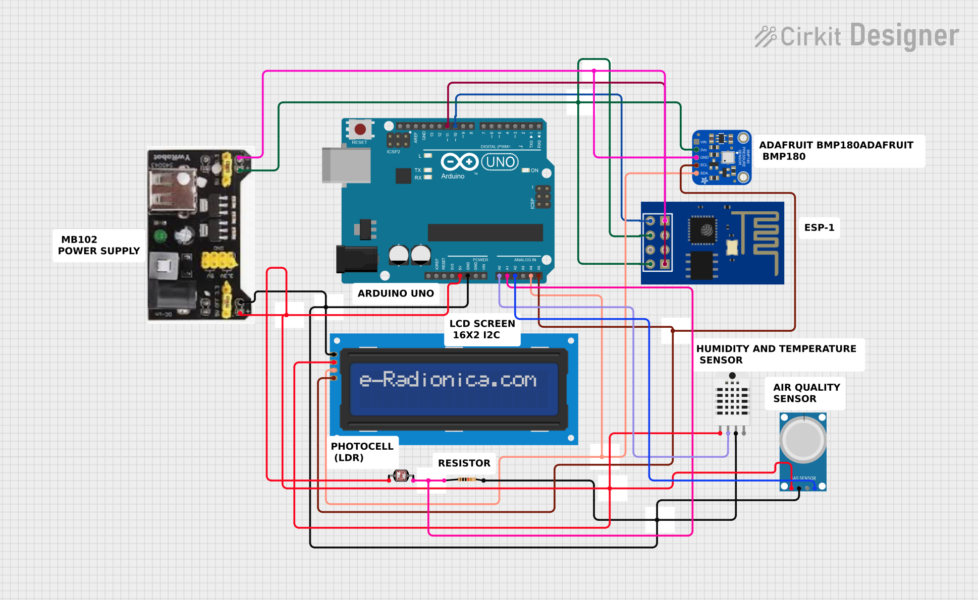
This document provides a detailed overview of a circuit that includes an Arduino UNO as the central microcontroller, interfaced with various sensors and modules including the Adafruit BMP180 barometric pressure sensor, ESP-01 WiFi module, a photocell (LDR), a DHT03 humidity and temperature sensor, an MQ-4 methane gas sensor, and a 16x2 LCD screen with I2C interface. The circuit is powered by an MB102 Breadboard Power Supply Module capable of providing both 3.3V and 5V outputs. A resistor is also included in the circuit for the photocell voltage divider.
Component List
Arduino UNO
- Microcontroller board based on the ATmega328P
- Features digital I/O pins, analog input pins, and various power pins
Adafruit BMP180
- Barometric pressure sensor
- Capable of measuring temperature as well
- Interfaces via I2C
ESP-01
- WiFi module based on the ESP8266
- Provides wireless connectivity to the circuit
Resistor
- Passive component used to limit current or divide voltages
- Resistance: 10,000 Ohms
Photocell (LDR)
- Light-dependent resistor
- Changes resistance based on the intensity of light
MB102 Breadboard Power Supply Module 3.3V/5V
- Provides regulated 3.3V and 5V to the breadboard
LCD screen 16x2 I2C
- Alphanumeric liquid crystal display
- 16 characters by 2 lines
- I2C interface for communication
Humidity and Temperature Sensor (DHT03)
- Measures ambient humidity and temperature
- Provides a digital signal output
MQ-4
- Methane gas sensor
- Analog and digital outputs
Wiring Details
Arduino UNO
5Vconnected to sensors and modules requiring 5VGNDconnected to common groundA0connected to DHT03 data signalA1connected to photocell (LDR)A2connected to MQ-4 analog outputA4(SDA) connected to I2C data lineA5(SCL) connected to I2C clock lineD10connected to ESP-01 TXD11connected to ESP-01 RX
Adafruit BMP180
SDAandSCLconnected to I2C bus+3V3andGNDconnected to 3.3V and ground from the power supply module
ESP-01
RXconnected to Arduino D11TXconnected to Arduino D10VCCandCH_PDconnected to 3.3VGNDconnected to common ground
Resistor (10k Ohms)
- One end connected to photocell (LDR) and Arduino A1
- Other end connected to common ground
Photocell (LDR)
- One end connected to 5V through a dot (junction point)
- Other end connected to Arduino A1 through a 10k Ohm resistor
MB102 Breadboard Power Supply Module 3.3V/5V
5voutput connected to 5V sensors and Arduino 5V3.3Voutput connected to 3.3V sensors and ESP-01GNDconnected to common ground
LCD screen 16x2 I2C
SDAandSCLconnected to I2C busVCCconnected to 5VGNDconnected to common ground
Humidity and Temperature Sensor (DHT03)
Vccconnected to 5VData-signalconnected to Arduino A0GND 1connected to common ground
MQ-4
A0connected to Arduino A2D0not connected in this circuitVCCconnected to 5VGNDconnected to common ground
Documented Code
Arduino UNO Code (sketch.ino)
void setup() {
  // put your setup code here, to run once:

}

void loop() {
  // put your main code here, to run repeatedly:

}
Note: The provided code is a template and does not include specific functionality. It needs to be populated with the setup and loop code to initialize and control the connected sensors and modules.