
Circuit Documentation
Summary of the Circuit
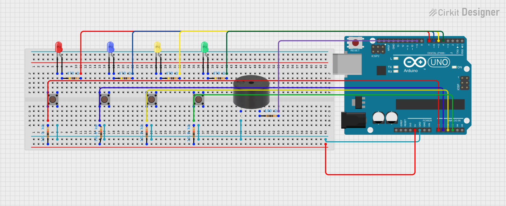
This circuit is designed around an Arduino UNO microcontroller, which serves as the central processing unit. The circuit includes a variety of components such as LEDs, resistors, pushbuttons, and a buzzer. The LEDs are used as indicators, and their operation is likely controlled by the Arduino UNO based on the input from the pushbuttons. The resistors are used to limit current to the LEDs and to provide pull-down functionality for the pushbuttons. The buzzer is included as an output device, potentially to provide audio feedback. The circuit's functionality is determined by the embedded code running on the Arduino UNO.
Component List
Arduino UNO
- Microcontroller board based on the ATmega328P
- Provides I/O pins for interfacing with other components
LED: Two Pin (green, yellow, red, blue)
- Light Emitting Diodes of various colors
- Used as visual indicators
Resistor (470 Ohms)
- Limits current to protect LEDs
Resistor (10,000 Ohms)
- Likely used as pull-down resistors for the pushbuttons
Resistor (100 Ohms)
- Current limiting resistor for the buzzer
Pushbutton
- Momentary tactile switch
- Used to provide user input to the circuit
Buzzer
- Audio signaling device
- Provides audible feedback when activated
Wiring Details
Arduino UNO
- A0, A1, A2, A3: Connected to pushbuttons through 10,000 Ohm resistors
- D4, D5, D6, D7: Connected to LEDs through 470 Ohm resistors
- D9: Connected to the buzzer through a 100 Ohm resistor
- 5V: Powers the 10,000 Ohm resistors connected to pushbuttons
- GND: Common ground for the circuit
LED: Two Pin (green, yellow, red, blue)
- Cathode: Connected to pushbuttons
- Anode: Connected to Arduino UNO through 470 Ohm resistors
Resistor (470 Ohms)
- One end connected to an LED anode
- Other end connected to a digital pin on the Arduino UNO
Resistor (10,000 Ohms)
- One end connected to 5V on the Arduino UNO
- Other end connected to a pushbutton and an analog pin on the Arduino UNO
Resistor (100 Ohms)
- One end connected to the buzzer
- Other end connected to D9 on the Arduino UNO
Pushbutton
- One side connected to a resistor and an analog pin on the Arduino UNO
- Other side connected to an LED cathode
Buzzer
- PIN: Connected to D9 on the Arduino UNO through a 100 Ohm resistor
- GND: Connected to the common ground
Documented Code
Arduino UNO Code (sketch.ino)
void setup() {
  // put your setup code here, to run once:

}

void loop() {
  // put your main code here, to run repeatedly:

}
Additional Notes (documentation.txt)
No additional code documentation provided.