
Arduino UNO Temperature Monitoring System with DS18B20 Sensor and LCD Display
View and Edit Project In Cirkit Designer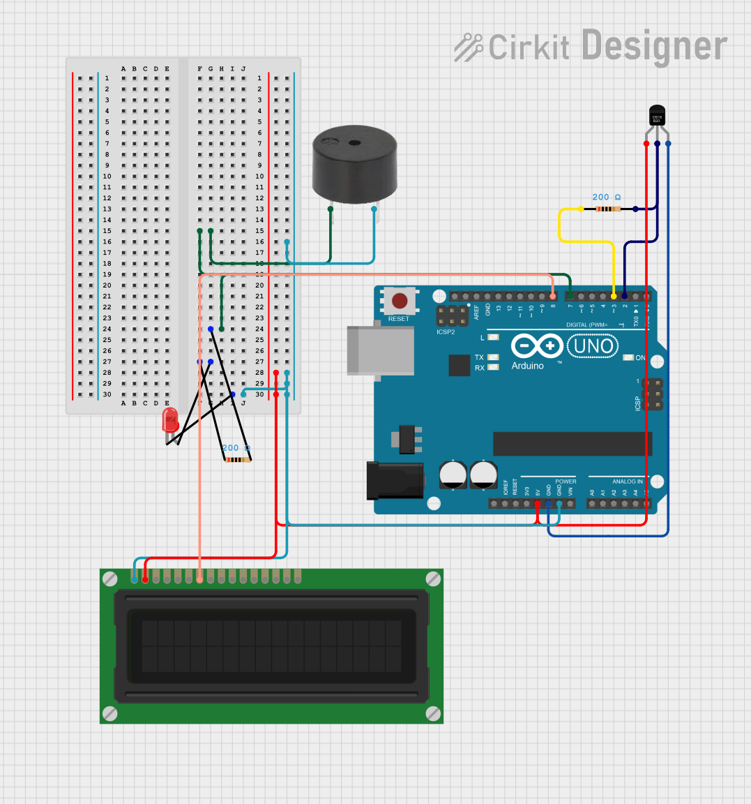
Circuit Documentation
Summary
This circuit involves an Arduino UNO microcontroller interfacing with a DS18B20 temperature sensor, a buzzer, an LED, two resistors, and an LCD display. The Arduino reads temperature data from the DS18B20 sensor and displays it on the LCD. Additionally, the buzzer and LED are used for alerting purposes.
Component List
Arduino UNO
- Description: A microcontroller board based on the ATmega328P.
- Pins: UNUSED, IOREF, Reset, 3.3V, 5V, GND, Vin, A0, A1, A2, A3, A4, A5, SCL, SDA, AREF, D13, D12, D11, D10, D9, D8, D7, D6, D5, D4, D3, D2, D1, D0
DS18B20
- Description: A digital temperature sensor.
- Pins: VDD, DQ, GND
Resistor (200 Ohms)
- Description: A resistor with a resistance of 200 Ohms.
- Pins: pin1, pin2
LED: Two Pin (red)
- Description: A red LED with two pins.
- Pins: cathode, anode
Buzzer
- Description: A simple buzzer.
- Pins: PIN, GND
LCD Display (16 pin)
- Description: A 16-pin LCD display.
- Pins: VSS, VDD, VO, RS, R_W, E, DB0, DB1, DB2, DB3, DB4, DB5, DB6, DB7, A, K
Wiring Details
Arduino UNO
- D2: Connected to
pin2of the 200 Ohms resistor (Resistor 1). - D3: Connected to
pin1of the 200 Ohms resistor (Resistor 1). - D7: Connected to
PINof the buzzer throughpin2of the 200 Ohms resistor (Resistor 2). - D8: Connected to
DB0of the LCD Display. - 5V: Connected to
VDDof the LCD Display andVDDof the DS18B20. - GND: Connected to
GNDof the DS18B20,GNDof the buzzer,VSSof the LCD Display, andcathodeof the LED.
DS18B20
- VDD: Connected to
5Vof the Arduino UNO. - DQ: Connected to
pin2of the 200 Ohms resistor (Resistor 1) andD2of the Arduino UNO. - GND: Connected to
GNDof the Arduino UNO.
Resistor (200 Ohms) - Resistor 1
- pin1: Connected to
D3of the Arduino UNO. - pin2: Connected to
DQof the DS18B20 andD2of the Arduino UNO.
Resistor (200 Ohms) - Resistor 2
- pin1: Connected to
anodeof the LED. - pin2: Connected to
PINof the buzzer andD7of the Arduino UNO.
LED: Two Pin (red)
- cathode: Connected to
GNDof the Arduino UNO. - anode: Connected to
pin1of the 200 Ohms resistor (Resistor 2).
Buzzer
- PIN: Connected to
pin2of the 200 Ohms resistor (Resistor 2) andD7of the Arduino UNO. - GND: Connected to
GNDof the Arduino UNO.
LCD Display (16 pin)
- VSS: Connected to
GNDof the Arduino UNO. - VDD: Connected to
5Vof the Arduino UNO. - DB0: Connected to
D8of the Arduino UNO.
Code Documentation
Main Sketch (sketch.ino)
/*
 * This Arduino sketch reads temperature data from a DS18B20 sensor
 * connected to pin D2 and prints the temperature to the serial console.
 * Pin D3 is set to HIGH to act as a pull-up resistor for the DS18B20 data line.
 */

#include "OneWire.h"
#include "DallasTemperature.h"

#define ONE_WIRE_BUS 2
#define PULLUP_PIN 3

OneWire oneWire(ONE_WIRE_BUS);
DallasTemperature sensors(&oneWire);

void setup() {
  // Set D3 as output and set it HIGH for pull-up
  pinMode(3, OUTPUT);
  digitalWrite(3, HIGH);

  // Start serial communication
  Serial.begin(9600);
  // Start up the library
  sensors.begin();
}

void loop() {
  // Request temperature readings
  sensors.requestTemperatures();
  // Fetch and print the temperature in Celsius
  Serial.println("here getting tempC by index");
  float temperatureC = sensors.getTempCByIndex(0);
  Serial.print("Temperature: ");
  Serial.print(temperatureC);
  Serial.println(" °C");
  // Wait 1 second before repeating
  delay(1000);
}
DallasTemperature Library (DallasTemperature.h)
#ifndef DallasTemperature_h
#define DallasTemperature_h

#define DALLASTEMPLIBVERSION "3.8.1" // To be deprecated -> TODO remove in 4.0.0

// This library is free software; you can redistribute it and/or
// modify it under the terms of the GNU Lesser General Public
// License as published by the Free Software Foundation; either
// version 2.1 of the License, or (at your option) any later version.

// set to true to include code for new and delete operators
#ifndef REQUIRESNEW
#define REQUIRESNEW false
#endif

// set to true to include code implementing alarm search functions
#ifndef REQUIRESALARMS
#define REQUIRESALARMS true
#endif

#include <inttypes.h>
#ifdef __STM32F1__
#include <OneWireSTM.h>
#else
#include "OneWire.h"
#endif

// Model IDs
#define DS18S20MODEL 0x10  // also DS1820
#define DS18B20MODEL 0x28  // also MAX31820
#define DS1822MODEL  0x22
#define DS1825MODEL  0x3B  // also MAX31850
#define DS28EA00MODEL 0x42

// Error Codes
#define DEVICE_DISCONNECTED_C -127
#define DEVICE_DISCONNECTED_F -196.6
#define DEVICE_DISCONNECTED_RAW -7040

#define DEVICE_FAULT_OPEN_C -254
#define DEVICE_FAULT_OPEN_F -425.199982
#define DEVICE_FAULT_OPEN_RAW -32512

#define DEVICE_FAULT_SHORTGND_C -253
#define DEVICE_FAULT_SHORTGND_F -423.399994
#define DEVICE_FAULT_SHORTGND_RAW -32384

#define DEVICE_FAULT_SHORTVDD_C -252
#define DEVICE_FAULT_SHORTVDD_F -421.599976
#define DEVICE_FAULT_SHORTVDD_RAW -32256

// For readPowerSupply on oneWire bus
#if __cplusplus < 201103L
const class
{
public:
    template <class T>
    operator T *() const {
        return 0;
    }

    template <class C, class T>
    operator T C::*() const {
        return 0;
    }

private:
    void operator&() const;
} nullptr = {};
#endif

typedef uint8_t DeviceAddress[8];

class DallasTemperature {
public:

    DallasTemperature();
    DallasTemperature(OneWire*);
    DallasTemperature(OneWire*, uint8_t);

    void setOneWire(OneWire*);

    void setPullupPin(uint8_t);

    // initialise bus
    void begin(void);

    // returns the number of devices found on the bus
    uint8_t getDeviceCount(void);

    // returns the number of DS18xxx Family devices on bus
    uint8_t getDS18Count(void);

    // returns true if address is valid
    bool validAddress(const uint8_t*);

    // returns true if address is of the family of sensors the lib supports.
    bool validFamily(const uint8_t* deviceAddress);

    // finds an address at a given index on the bus
    bool getAddress(uint8_t*, uint8_t);

    // attempt to determine if the device at the given address is connected to the bus
    bool isConnected(const uint8_t*);

    // attempt to determine if the device at the given address is connected to the bus
    // also allows for updating the read scratchpad
    bool isConnected(const uint8_t*, uint8_t*);

    // read device's scratchpad
    bool readScratchPad(const uint8_t*, uint8_t*);

    // write device's scratchpad
    void writeScratchPad(const uint8_t*,