
Battery-Powered LED Circuit with Polarity Protection and Power Switch
View and Edit Project In Cirkit Designer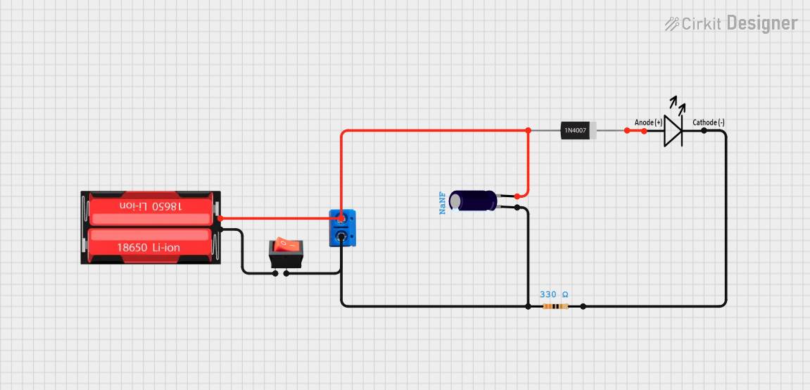
Circuit Documentation
Summary of the Circuit
The circuit described by the provided inputs appears to be a simple power supply circuit with an LED indicator. The circuit includes a power source (18650 Li-Ion battery), a current-limiting resistor, an LED, a rectifier diode to prevent reverse current, an electrolytic capacitor for voltage smoothing, a rocker switch for power control, and a terminal PCB for external connections. The circuit does not include any microcontroller or embedded code.
Component List
LED
- Description: A light-emitting diode used as an indicator.
- Pins: Anode (+), Cathode (-)
Terminal PCB 2 Pin
- Description: A two-pin terminal for making external connections to the circuit.
- Pins: Pin A, Pin B
Electrolytic Capacitor
- Description: A capacitor used for filtering and stabilizing the DC power supply.
- Pins: Anode (+), Cathode (-)
- Properties: Capacitance (Value not specified)
1N4007 Rectifier Diode
- Description: A diode used to prevent reverse current flow.
- Pins: Anode, Cathode
18650 Li-Ion Battery
- Description: A rechargeable lithium-ion battery used as the power source.
- Pins: Positive, Negative
Rocker Switch
- Description: A switch used to control the power flow in the circuit.
- Pins: Input, Output
Resistor
- Description: A resistor used to limit the current through the LED.
- Pins: Pin 1, Pin 2
- Properties: Resistance: 330 Ohms
Wiring Details
LED
- Anode (Positive) connected to the Cathode of the 1N4007 Rectifier Diode.
- Cathode (Negative) connected to Pin 2 of the Resistor.
Terminal PCB 2 Pin
- Pin A connected to the Positive pin of the 18650 Li-Ion Battery, Anode of the Electrolytic Capacitor, and Anode of the 1N4007 Rectifier Diode.
- Pin B connected to the Negative pin of the Electrolytic Capacitor, Output of the Rocker Switch, and Pin 1 of the Resistor.
Electrolytic Capacitor
- Anode (Positive) connected to the Positive pin of the 18650 Li-Ion Battery, Pin A of the Terminal PCB 2 Pin, and Anode of the 1N4007 Rectifier Diode.
- Cathode (Negative) connected to the Output of the Rocker Switch, Pin B of the Terminal PCB 2 Pin, and Pin 1 of the Resistor.
1N4007 Rectifier Diode
- Anode connected to the Positive pin of the 18650 Li-Ion Battery, Pin A of the Terminal PCB 2 Pin, and Anode of the Electrolytic Capacitor.
- Cathode connected to the Anode of the LED.
18650 Li-Ion Battery
- Positive connected to the Anode of the Electrolytic Capacitor, Pin A of the Terminal PCB 2 Pin, and Anode of the 1N4007 Rectifier Diode.
- Negative connected to the Input of the Rocker Switch.
Rocker Switch
- Input connected to the Negative pin of the 18650 Li-Ion Battery.
- Output connected to the Negative pin of the Electrolytic Capacitor, Pin B of the Terminal PCB 2 Pin, and Pin 1 of the Resistor.
Resistor
- Pin 1 connected to the Output of the Rocker Switch, Pin B of the Terminal PCB 2 Pin, and Cathode of the Electrolytic Capacitor.
- Pin 2 connected to the Cathode of the LED.
Documented Code
There is no embedded code provided for this circuit as it does not include any programmable components or microcontrollers.