
ESP8266 NodeMCU Controlled Water Flow Monitoring and Leak Detection System
View and Edit Project In Cirkit Designer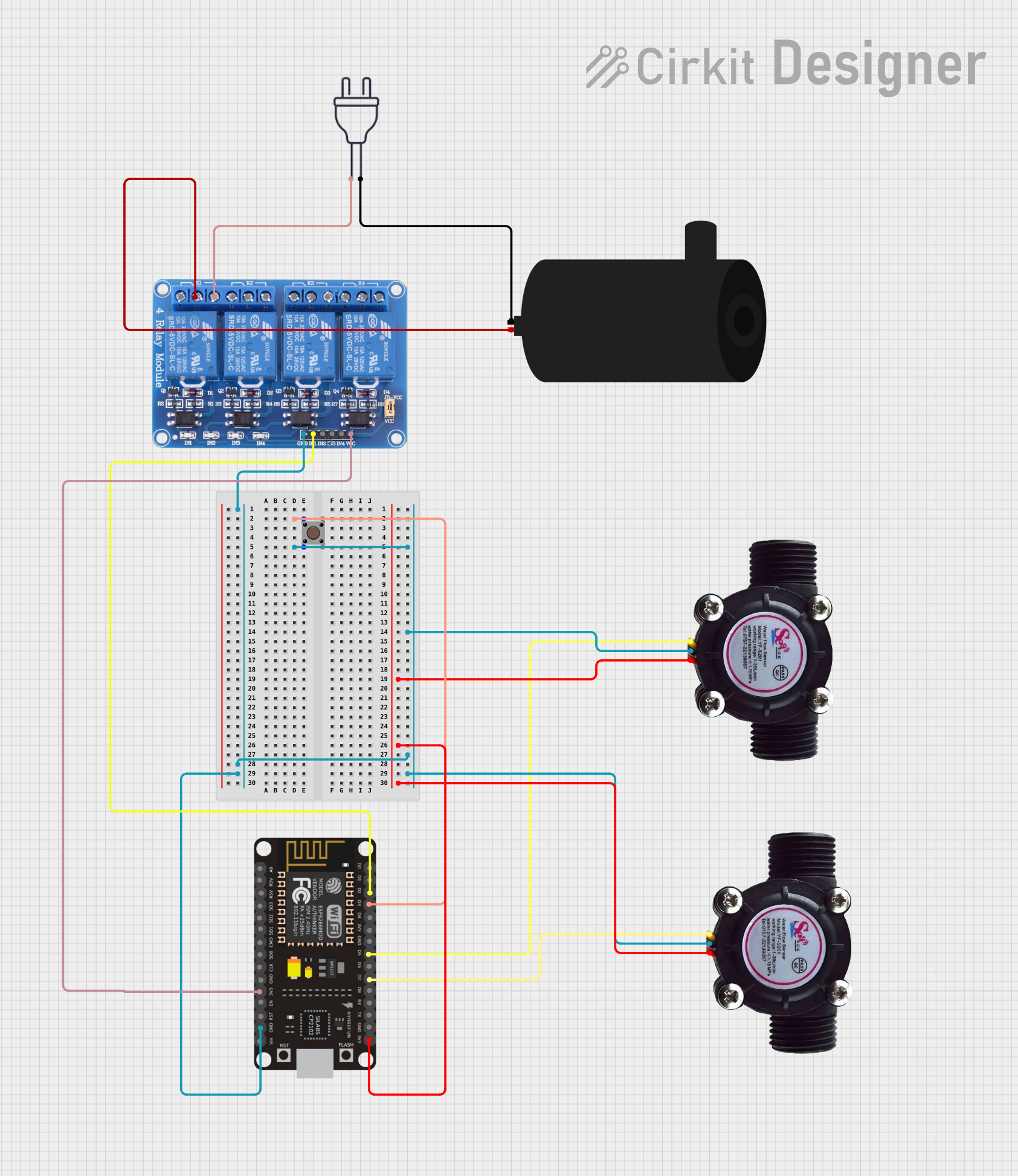
Circuit Documentation
Summary
This circuit is designed to monitor and control water flow using an ESP8266 NodeMCU microcontroller. It includes two water flow sensors to measure the flow rate, a pushbutton to manually start and stop the water flow, a relay to control a water pump, and a power supply to drive the pump. The ESP8266 NodeMCU is programmed to read the flow rates from the sensors, control the relay based on the pushbutton input, and automatically stop the water flow if a leak is detected.
Component List
ESP8266 NodeMCU
- Microcontroller with WiFi capability.
- Pins: D0, D1, D2, D3, D4, 3V3, GND, D5, D6, D7, D8, RX, TX, A0, RSV, SD3, SD2, SD1, CMD, SD0, CLK, EN, RST, VIN.
Pushbutton
- A simple pushbutton switch.
- Pins: Pin 3 (out), Pin 4 (out), Pin 1 (in), Pin 2 (in).
Water Flow Sensor (x2)
- Sensors to measure the flow rate of water.
- Pins: Signal, Vcc, GND.
Water Pump
- A pump to move water through the system.
- Pins: positive, negative.
Relay 4 Channel 5v
- A 4-channel relay module to control high power devices.
- Pins: GND, IN1, IN2, IN3, IN4, VCC, COM1, COM2, COM3, COM4, NO1, NO2, NO3, NO4, NC1, NC2, NC3, NC4.
Power 220v
- A power supply to provide 220V AC.
- Pins: hot wire, neutral wire.
Wiring Details
ESP8266 NodeMCU
- D3 connected to Pushbutton (Pin 1 (in))
- GND connected to:
- Pushbutton (Pin 2 (in))
- Water Flow Sensor (GND)
- Relay 4 Channel 5v (GND)
- 3V3 connected to:
- Water Flow Sensor (Vcc)
- Relay 4 Channel 5v (VCC)
- D2 connected to Relay 4 Channel 5v (IN1)
- D5 connected to Water Flow Sensor (Signal)
- D7 connected to Water Flow Sensor (Signal)
Pushbutton
- Pin 1 (in) connected to ESP8266 NodeMCU (D3)
- Pin 2 (in) connected to GND
Water Flow Sensor
- Signal connected to ESP8266 NodeMCU (D5 or D7)
- Vcc connected to ESP8266 NodeMCU (3V3)
- GND connected to GND
Water Pump
- positive connected to Relay 4 Channel 5v (COM1)
- negative connected to Power 220v (neutral wire)
Relay 4 Channel 5v
- GND connected to GND
- IN1 connected to ESP8266 NodeMCU (D2)
- VCC connected to ESP8266 NodeMCU (3V3)
- COM1 connected to Water Pump (positive)
- NO1 connected to Power 220v (hot wire)
Power 220v
- neutral wire connected to Water Pump (negative)
- hot wire connected to Relay 4 Channel 5v (NO1)
Documented Code
const int flowSensor1Pin = D7;
const int flowSensor2Pin = D5;
const int relayPin = D2;
int flag = 0;
int Bvar = D3;

volatile int pulseCount1 = 0;
volatile int pulseCount2 = 0;
float flowRate1 = 0.0;
float flowRate2 = 0.0;
const float calibrationFactor = 7.5;
unsigned long lastPulseTime = 0;
const unsigned long interval = 3000;
int flowDifference = 0;
bool leakDetected = false;  // Variable to determine if a leak has been detected

void ICACHE_RAM_ATTR pulseCounter1() {
  pulseCount1++;
}

void ICACHE_RAM_ATTR pulseCounter2() {
  pulseCount2++;
}

void setup() {
  Serial.begin(115200);

  pinMode(flowSensor1Pin, INPUT);
  pinMode(flowSensor2Pin, INPUT);
  pinMode(Bvar, INPUT);

  pinMode(relayPin, OUTPUT);
  digitalWrite(relayPin, HIGH);

  attachInterrupt(digitalPinToInterrupt(flowSensor1Pin), pulseCounter1, FALLING);
  attachInterrupt(digitalPinToInterrupt(flowSensor2Pin), pulseCounter2, FALLING);
}

void loop() {
  unsigned long currentTime = millis();
  int buttonState = digitalRead(Bvar);

  if (leakDetected) {
      Serial.println("Leak Detected! Water flow stopped.");
      digitalWrite(relayPin, HIGH); // Stop water flow
      Serial.println("WARNING: Water flow has been stopped due to a detected leak!"); // Warning
  } else {
      if (buttonState == LOW) {
          digitalWrite(relayPin, LOW);
          Serial.println("Water Flow Started");
      } else {
          digitalWrite(relayPin, HIGH);
          Serial.println("Water Flow Stopped");
      }
  }

  if (currentTime - lastPulseTime >= interval) {
    noInterrupts();

    flowRate1 = (pulseCount1 / calibrationFactor);
    flowRate2 = (pulseCount2 / calibrationFactor);
    pulseCount1 = 0;
    pulseCount2 = 0;
    flowDifference = flowRate2 - flowRate1;

    interrupts();

    Serial.print("Flow Rate 1: ");
    Serial.print(flowRate1);
    Serial.println(" L/min");
    Serial.print("Flow Rate 2: ");
    Serial.print(flowRate2);
    Serial.println(" L/min");

    if (flowDifference >= 1000) {  // Threshold changed to 1000 L/min
        leakDetected = true;  // Leak detected
        Serial.println("Leak Detected! Water flow stopped.");
        digitalWrite(relayPin, HIGH); // Automatically stop water flow
        Serial.println("WARNING: Water flow has been stopped due to a detected leak!"); // Warning
    } else if (buttonState == LOW) {
        if (relayPin == HIGH)
          flag = 0;
        else
          flag = 1;
        switch (flag) {
          case 0:
            digitalWrite(relayPin, LOW);
            Serial.println(" System Stable");
            delay(1000);
            break;
          case 1:
            digitalWrite(relayPin, HIGH);
            Serial.println(" System Not Stable");
            flag = 0;
            delay(1000);
            break;
        }
        delay(200);
    } else {
        if (flowDifference >= 1000) {  // Threshold updated to 1000 L/min
          digitalWrite(relayPin, HIGH); // Automatically stop water
          Serial.println("System Failure - Water flow stopped");
          delay(1000);
        } else {
          digitalWrite(relayPin, HIGH);
          Serial.println("System Failure");
          delay(1000);
        }
    }

    lastPulseTime = currentTime;
  }
}
This code is responsible for reading the water flow rates from the sensors, controlling the relay based on the pushbutton state, and automatically stopping the water flow if a significant difference in flow rates is detected, indicating a potential leak. The relay is controlled to start or stop the water pump, and the system status is communicated via serial output.