
Circuit Documentation
Summary
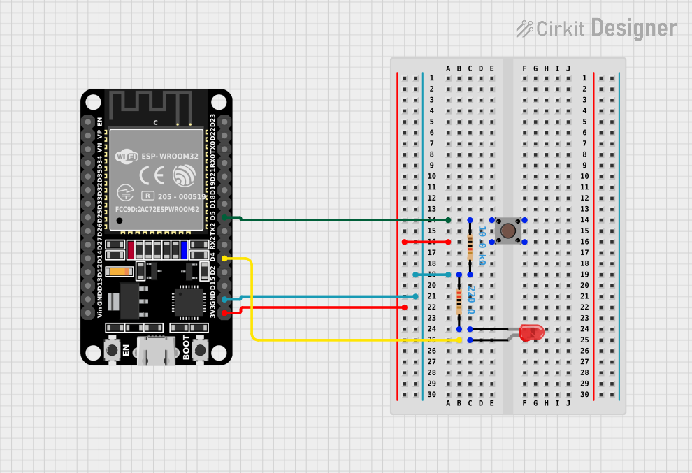
This circuit is designed around the ESP32 microcontroller, which is a versatile and powerful microcontroller with a wide range of I/O capabilities. The circuit includes a pushbutton that allows user interaction, a resistor to limit current through the pushbutton, an LED to provide visual feedback, and another resistor to limit current through the LED. The ESP32 reads the state of the pushbutton and controls the LED accordingly. The circuit is powered by the 3.3V supply from the ESP32.
Component List
ESP32 (30 pin)
- Description: A 30-pin ESP32 microcontroller module.
- Purpose: Acts as the central processing unit of the circuit, reading input from the pushbutton and controlling the LED output.
Pushbutton
- Description: A standard pushbutton with four pins.
- Purpose: Provides a user interface to control the circuit.
Resistor (10k Ohms)
- Description: A resistor with a resistance of 10,000 Ohms.
- Purpose: Limits the current flowing through the pushbutton to protect the ESP32 input pin.
LED: Two Pin (red)
- Description: A two-pin red LED.
- Purpose: Serves as an indicator light that is controlled by the ESP32.
Resistor (220 Ohms)
- Description: A resistor with a resistance of 220 Ohms.
- Purpose: Limits the current flowing through the LED to prevent damage.
Wiring Details
ESP32 (30 pin)
- EN: Not connected in this circuit.
- VP: Not connected in this circuit.
- VN: Not connected in this circuit.
- D34-D33, D25-D27, D14-D13, Vin, D23-D22, TX0-RX0, D21-D19, D18, TX2-RX2, D2, D15: Not connected in this circuit.
- D4: Connected to the anode of the LED.
- D5: Connected to one side of the pushbutton and to one side of the 10k Ohm resistor.
- 3V3: Connected to the other side of the pushbutton.
- GND: Connected to one side of the 220 Ohm resistor and to the other side of the 10k Ohm resistor.
Pushbutton
- Pin 3 (out): Connected to the 10k Ohm resistor and to pin D5 of the ESP32.
- Pin 1 (in): Connected to the 3V3 supply of the ESP32.
- Pin 4 (out), Pin 2 (in): Not connected in this circuit.
Resistor (10k Ohms)
- pin1: Connected to the pushbutton and to pin D5 of the ESP32.
- pin2: Connected to the GND of the ESP32.
LED: Two Pin (red)
- anode: Connected to pin D4 of the ESP32.
- cathode: Connected to the 220 Ohm resistor.
Resistor (220 Ohms)
- pin1: Connected to the cathode of the LED.
- pin2: Connected to the GND of the ESP32.
Documented Code
// Code for ESP32 microcontroller
int onOff = LOW;
long lastPrint = 0;

void setup() {
  // Initialize serial communication at 115200 bits per second:
  Serial.begin(115200);

  // Set pin D4 as an OUTPUT for the LED control:
  pinMode(4, OUTPUT);

  // Set pin D5 as an INPUT for reading the pushbutton state:
  pinMode(5, INPUT);
}

void loop() {
  // Read the state of the pushbutton:
  int btn = digitalRead(5);

  // If the button state has changed, update the LED state and store the new state:
  if(btn != onOff) {
    digitalWrite(4, btn);
    onOff = btn;
  }

  // Every 1000 milliseconds, print the state of the button:
  long currentMillis = millis();
  if(currentMillis - lastPrint > 1000) {
    Serial.println(onOff ? "on" : "off");
    lastPrint = currentMillis;
  }
}
This code is designed to run on the ESP32 microcontroller. It initializes the serial communication for debugging purposes and sets up the necessary pins for the LED and pushbutton. The loop function continuously checks the state of the pushbutton and toggles the LED accordingly. It also prints the state of the LED to the serial monitor every second.