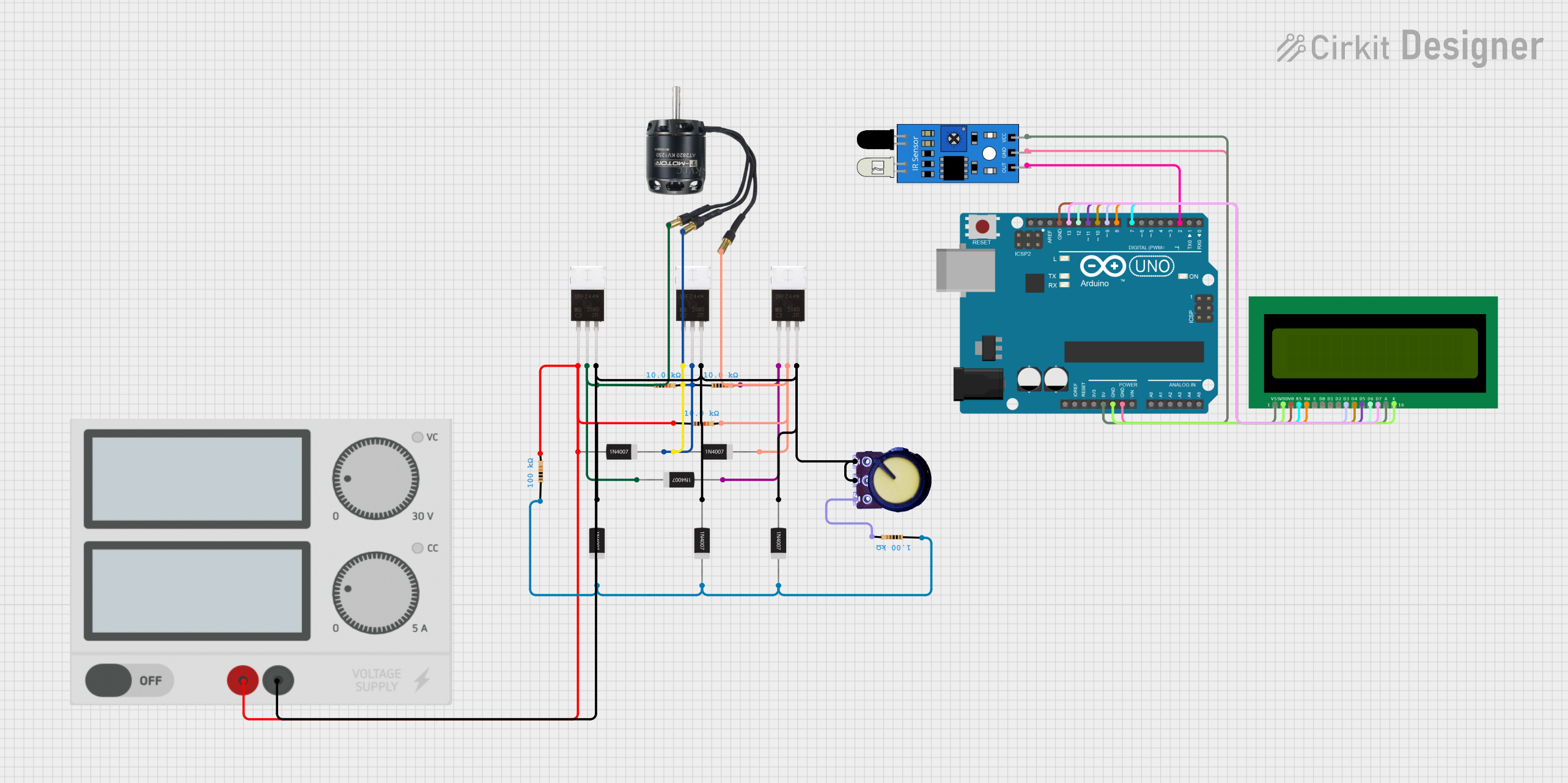
Arduino UNO Controlled BLDC Motor with RPM Display and IR Sensor Feedback

Circuit Documentation
Summary
This circuit is designed to control a Brushless DC (BLDC) motor using an Arduino UNO microcontroller. The system includes an IR sensor for RPM measurement, a potentiometer for speed control, and a 16x2 LCD display for showing the RPM of the motor. The motor's speed is controlled by PWM signals generated by the Arduino, which are then fed to the motor through a set of IRFZ44N MOSFETs. Diodes are used for flyback protection. The circuit is powered by an external power supply.
Component List
Microcontroller
- Arduino UNO: A microcontroller board based on the ATmega328P. It has digital input/output pins, analog inputs, a USB connection for programming, and power management features.
Sensors
- IR Sensor: An infrared sensor used for detecting the RPM of the BLDC motor.
Display
- 16X2 LCD: A liquid crystal display capable of displaying 16 characters per line across 2 lines.
Passive Components
- Potentiometer: A variable resistor with three terminals, used to adjust the motor speed.
- Resistors: Various resistors with different resistance values (1kΩ, 10kΩ, 100kΩ) used for current limiting and voltage division.
Semiconductors
- 1N4007 Rectifier Diodes: General-purpose diodes used for flyback protection in the motor control circuit.
- IRFZ44N: Power MOSFETs used as switches to control the power to the BLDC motor.
Power Supply
- Power Supply: Provides the necessary voltage and current to power the circuit.
Actuator
- BLDC Motor: A brushless DC motor that is controlled by the Arduino through the MOSFETs.
Wiring Details
Arduino UNO
- 5V to 16X2 LCD VSS, A, and IR Sensor VCC.
- GND to 16X2 LCD VDD, K, V0, and IR Sensor GND.
- D13 to 16X2 LCD D7.
- D12 to 16X2 LCD D6.
- D11 to 16X2 LCD D5.
- D10 to 16X2 LCD D4.
- D9 to 16X2 LCD D3.
- D8 to 16X2 LCD RW.
- D7 to 16X2 LCD RS.
- D2 to IR Sensor OUT.
IR Sensor
- OUT to Arduino D2.
- GND to Arduino GND.
- VCC to Arduino 5V.
16X2 LCD
- VSS, A to Arduino 5V.
- VDD, K to Arduino GND.
- V0 to Arduino GND.
- RS to Arduino D7.
- RW to Arduino D8.
- D3 to Arduino D9.
- D4 to Arduino D10.
- D5 to Arduino D11.
- D6 to Arduino D12.
- D7 to Arduino D13.
Potentiometer
- GND to Power Supply -.
- Output to Arduino A0.
- VCC to one terminal of a 1kΩ resistor (other terminal to Power Supply +).
Resistors
- 10kΩ between BLDC Motor Wire A and IRFZ44N Drain, between BLDC Motor Wire B and IRFZ44N Drain, and between BLDC Motor Wire C and IRFZ44N Drain.
- 1kΩ between Potentiometer VCC and Power Supply +.
- 100kΩ between Power Supply + and IRFZ44N Gate.
Diodes
- 1N4007 with Cathode to BLDC Motor Wires A, B, C, and Anode to Power Supply -.
IRFZ44N
- Gate connected to Power Supply + through a 100kΩ resistor.
- Drain connected to BLDC Motor Wires A, B, C through 10kΩ resistors.
- Source connected to Power Supply -.
BLDC Motor
- Wire A, B, C connected to IRFZ44N Drain through 10kΩ resistors.
Power Supply
- + to Potentiometer VCC through a 1kΩ resistor and to IRFZ44N Gate through a 100kΩ resistor.
- - to Arduino GND, 16X2 LCD VDD, K, V0, IR Sensor GND, Potentiometer GND, and IRFZ44N Source.
Documented Code
#include <LiquidCrystal.h>

// Initialize the LCD library with the numbers of the interface pins
LiquidCrystal lcd(7, 8, 4, 5, 6, 3);

const int potPin = A0; // Potentiometer pin
const int motorPin1 = 9; // MOSFET gate pin for BLDC motor
const int motorPin2 = 10; // MOSFET gate pin for BLDC motor
const int motorPin3 = 11; // MOSFET gate pin for BLDC motor
const int irSensorPin = 2; // IR sensor pin

volatile unsigned long rpmCount = 0;
unsigned long lastTime = 0;
unsigned long rpm = 0;

void setup() {
  // Set up the LCD's number of columns and rows:
  lcd.begin(16, 2);
  lcd.print("RPM: ");

  pinMode(motorPin1, OUTPUT);
  pinMode(motorPin2, OUTPUT);
  pinMode(motorPin3, OUTPUT);
  pinMode(irSensorPin, INPUT);

  attachInterrupt(digitalPinToInterrupt(irSensorPin), rpmCounter, RISING);
}

void loop() {
  int potValue = analogRead(potPin);
  int motorSpeed = map(potValue, 0, 1023, 0, 255);

  analogWrite(motorPin1, motorSpeed);
  analogWrite(motorPin2, motorSpeed);
  analogWrite(motorPin3, motorSpeed);

  unsigned long currentTime = millis();
  if (currentTime - lastTime >= 1000) {
    noInterrupts();
    rpm = rpmCount * 60; // Convert to RPM
    rpmCount = 0;
    lastTime = currentTime;
    interrupts();

    lcd.setCursor(0, 1);
    lcd.print(rpm);
    lcd.print("    "); // Clear any extra characters
  }
}

void rpmCounter() {
  rpmCount++;
}
This code is responsible for reading the potentiometer value to control the speed of the BLDC motor, measuring the RPM using an IR sensor, and displaying the RPM on a 16x2 LCD. The setup() function initializes the LCD and configures the pins. The loop() function reads the potentiometer, maps its value to a PWM signal, and writes it to the motor control pins. It also calculates and displays the RPM every second. The rpmCounter() function is an interrupt service routine that increments the RPM count every time the IR sensor detects a rotation.