
ESP32-Based GPS Tracker with Vibration Sensor and LCD Display
View and Edit Project In Cirkit Designer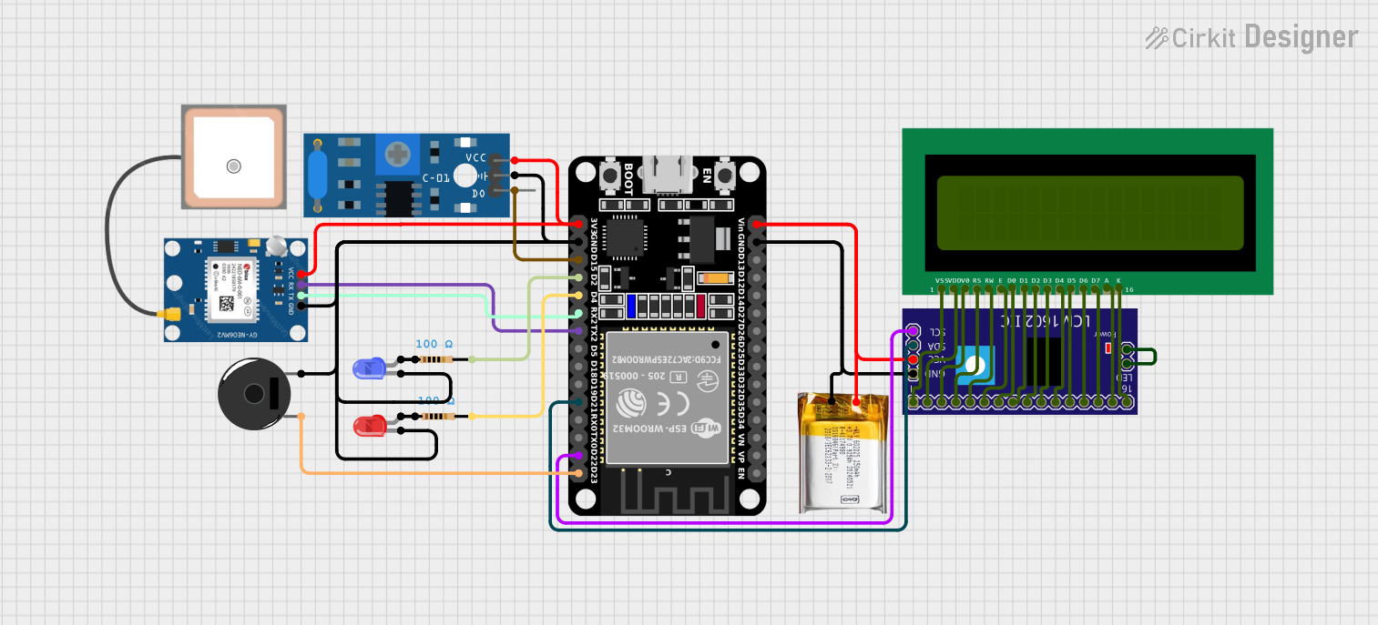
Circuit Documentation
Summary
This document provides a detailed overview of a circuit that integrates an ESP32 microcontroller with various sensors and output devices. The circuit includes a GPS module, a vibration sensor, an LCD display, LEDs, a piezo buzzer, and a power source. The ESP32 is programmed to read data from the GPS module and display it on the LCD.
Component List
ESP32 (30 pin)
- Description: A powerful microcontroller with built-in Wi-Fi and Bluetooth capabilities.
- Pins: EN, VP, VN, D34, D35, D32, D33, D25, D26, D27, D14, D12, D13, GND, Vin, D23, D22, TX0, RX0, D21, D19, D18, D5, TX2, RX2, D4, D2, D15, 3V3
SW-420 Vibration Sensor
- Description: A sensor that detects vibrations and outputs a digital signal.
- Pins: vcc, Ground, Digital output
16X2 LCD
- Description: A 16x2 character LCD display.
- Pins: VSS, VDD, V0, RS, RW, E, D1, D0, D2, D3, D4, D6, D5, D7, A, K
LCM1602 IIC
- Description: An I2C interface for the 16x2 LCD display.
- Pins: GND, VCC, SDA, SCL, D6, D7, A, K, VSS, VDD, V0, RS, D2, D3, D4, D5, RW, E, D0, D1, LED_A, LED_B
GPS NEO 6M
- Description: A GPS module for receiving location data.
- Pins: VCC, RX, TX, GND
Piezo Buzzer
- Description: A buzzer that produces sound when a voltage is applied.
- Pins: pin 1, pin 2
Resistor (100 Ohms)
- Description: A resistor with a resistance of 100 Ohms.
- Pins: pin1, pin2
LED: Two Pin (blue)
- Description: A blue LED.
- Pins: cathode, anode
LED: Two Pin (red)
- Description: A red LED.
- Pins: cathode, anode
3.7v LiPo
- Description: A 3.7V Lithium Polymer battery.
- Pins: +Ve, GND
Wiring Details
ESP32 (30 pin)
- GND: Connected to GND of LCM1602 IIC, GND of 3.7v LiPo, GND of SW-420 Vibration Sensor, GND of GPS NEO 6M, GND of Piezo Buzzer, cathode of LED: Two Pin (red), and cathode of LED: Two Pin (blue).
- Vin: Connected to VCC of LCM1602 IIC and +Ve of 3.7v LiPo.
- D23: Connected to pin 1 of Piezo Buzzer.
- D22: Connected to SCL of LCM1602 IIC.
- D21: Connected to SDA of LCM1602 IIC.
- TX2: Connected to RX of GPS NEO 6M.
- RX2: Connected to TX of GPS NEO 6M.
- D4: Connected to pin2 of Resistor (100 Ohms).
- D2: Connected to pin2 of another Resistor (100 Ohms).
- D15: Connected to Digital output of SW-420 Vibration Sensor.
- 3V3: Connected to vcc of SW-420 Vibration Sensor and VCC of GPS NEO 6M.
SW-420 Vibration Sensor
- vcc: Connected to 3V3 of ESP32.
- Ground: Connected to GND of ESP32.
- Digital output: Connected to D15 of ESP32.
16X2 LCD
- VSS: Connected to VSS of LCM1602 IIC.
- VDD: Connected to VDD of LCM1602 IIC.
- V0: Connected to V0 of LCM1602 IIC.
- RS: Connected to RS of LCM1602 IIC.
- RW: Connected to RW of LCM1602 IIC.
- E: Connected to E of LCM1602 IIC.
- D1: Connected to D1 of LCM1602 IIC.
- D0: Connected to D0 of LCM1602 IIC.
- D2: Connected to D2 of LCM1602 IIC.
- D3: Connected to D3 of LCM1602 IIC.
- D4: Connected to D4 of LCM1602 IIC.
- D6: Connected to D6 of LCM1602 IIC.
- D5: Connected to D5 of LCM1602 IIC.
- D7: Connected to D7 of LCM1602 IIC.
- A: Connected to A of LCM1602 IIC.
- K: Connected to K of LCM1602 IIC.
LCM1602 IIC
- GND: Connected to GND of ESP32 and GND of 3.7v LiPo.
- VCC: Connected to Vin of ESP32 and +Ve of 3.7v LiPo.
- SDA: Connected to D21 of ESP32.
- SCL: Connected to D22 of ESP32.
- VSS: Connected to VSS of 16X2 LCD.
- VDD: Connected to VDD of 16X2 LCD.
- V0: Connected to V0 of 16X2 LCD.
- RS: Connected to RS of 16X2 LCD.
- RW: Connected to RW of 16X2 LCD.
- E: Connected to E of 16X2 LCD.
- D1: Connected to D1 of 16X2 LCD.
- D0: Connected to D0 of 16X2 LCD.
- D2: Connected to D2 of 16X2 LCD.
- D3: Connected to D3 of 16X2 LCD.
- D4: Connected to D4 of 16X2 LCD.
- D6: Connected to D6 of 16X2 LCD.
- D5: Connected to D5 of 16X2 LCD.
- D7: Connected to D7 of 16X2 LCD.
- A: Connected to A of 16X2 LCD.
- K: Connected to K of 16X2 LCD.
- LED_A: Connected to LED_B of LCM1602 IIC.
GPS NEO 6M
- VCC: Connected to 3V3 of ESP32.
- RX: Connected to TX2 of ESP32.
- TX: Connected to RX2 of ESP32.
- GND: Connected to GND of ESP32.
Piezo Buzzer
- pin 1: Connected to D23 of ESP32.
- pin 2: Connected to GND of ESP32.
Resistor (100 Ohms)
- pin1: Connected to anode of LED: Two Pin (red).
- pin2: Connected to D4 of ESP32.
Resistor (100 Ohms)
- pin1: Connected to anode of LED: Two Pin (blue).
- pin2: Connected to D2 of ESP32.
LED: Two Pin (blue)
- cathode: Connected to GND of ESP32.
- anode: Connected to pin1 of Resistor (100 Ohms).
LED: Two Pin (red)
- cathode: Connected to GND of ESP32.
- anode: Connected to pin1 of Resistor (100 Ohms).
3.7v LiPo
- +Ve: Connected to Vin of ESP32 and VCC of LCM1602 IIC.
- GND: Connected to GND of ESP32 and GND of LCM1602 IIC.
Code Documentation
ESP32 Code
#include <TinyGPS++.h>
#include <TinyGPSPlus.h>

#define GPS_BAUDRATE 9600  // The default baudrate of NEO-6M is 9600

TinyGPSPlus gps;  // the TinyGPS++ object

void setup() {
  Serial.begin(9600);
  Serial2.begin(GPS_BAUDRATE); // serial2 for GPS UART

  Serial.println(F("ESP32 -